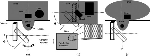
Fig. 3.
Illustration of simulation geometry including radiopaque patient bed. (a) Lateral view of simulated prone patient geometry indicating the polar tilting angle () of the detector. (b) Posterior–anterior view of geometry indicating the azimuthal rotation angle () and illustration of the hexagonal parallel-hole collimator. (c) Superior–inferior view showing the intersection of the elliptical-cylinder torso and breast.

