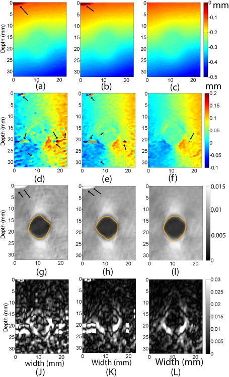
Fig. 2.
Images of the tissue mimicking phantom containing a spherical target using three different subsample displacement estimation methods. Images in the first, second and third columns were obtained using the 1D quadratic interpolation method, the 2D quadratic interpolation method, and the coupled tracking method, respectively. The top row, (a) - (c), is axial displacement images, while (d) - (f) are lateral displacement images, (g)-(I) are axial strain images and (J)-(L) are (full) shear strain images. The arrows on all images point to potential tracking errors. The contours in axial strain images segment target boundaries and were used for calculations of CNRs. A 3 × 3 median filter was applied to lateral displacement estimates for display.

