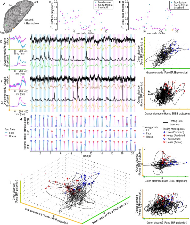
Fig 6. A combined ERBB-broadband and ERP-voltage projection feature space for classification (subject 5).
(A) Two cortical sites (orange and green dots) are examined. (B) The axes show the (blue asterisk) and (pink box) for ERP-voltage training projections show that these orange and green sites are highly selective during the training period (from first cross-fold). (C) for ERBB-Broadband training projections. (D) Averaged face and house ERP templates from the green site are shown on the left axes (olive green). The face-ERP templates are projected into the raw voltage trace (black) to obtain continuous a projection weight trace (olive green trace). (E) As in (D), but for ERBB-broadband templates in the green electrode site (neon green). (F&G) As in (D&E), except for the orange electrode site in (A), using house ERP (brown) and ERBB (burned orange) templates. (H) Green electrode, face ERP vs ERBB subspace projections. (I) Orange electrode house ERP vs ERBB subspace projections. (J) ERBB projection subspace (orange-electrode house-template projection vs green-electrode face-template projection). (K) As in (J), for ERP projection subspace. (L) A 3-d subspace projection (features from D,E,G). (M) Posterior probability of a face, Pr{Γm(t)|q → F} (blue), or house stimulus, Pr{Γm(t)|q → F} (pink), having been presented (where m → ERP, ERBB or both features for the projection space).

