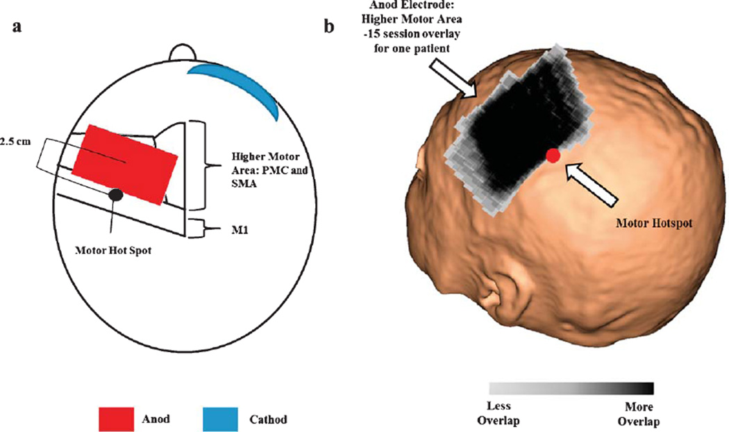
Fig. 3.
a) figure adapted from Pavlova et al. 2014. Shows the location of the anod electrode relative to the motor hotspot. b) tDCS anod electrode placement overlay of 15 individual therapy session for one patient. Across all patients, the center of the anodal electrode was placed 26.78 ± 8.6 mm from the patients’ motor hotspot. The black region represents the most consistent placement of the tDCS electrode throughout the 15 sessions of therapy. The motor hotspot is represented as the red circle.

