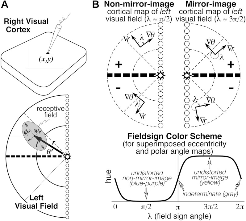
Fig. 1.
(A) Seven receptive field parameters (digitized on a sphere). Receptive field center is defined by (r, θ), size, and shape by (l, w, φ), and cortical recording site location by (x, y). An arrow diagram is made by placing a scaled copy of the thick arrow from the center of gaze (star) to the receptive field center at the x–y position on the cortex where that receptive field was recorded. (B) Local visual field sign of a cortical retinotopic map of the left hemifield is the (clockwise) angle, λ, between the direction of the eccentricity gradient (grad r) on the cortex, and the direction of the polar angle gradient (grad θ) (lower to horizontal to upper) on the cortex. An angle near 90 deg (0 < λ < π) signifies a nonmirror image map of the left hemifield while an angle near 270 deg (π < λ < 2π) signifies a mirror image map of the left hemifield. Visual field sign is invariant to rotations and distortions of cortical maps but also invariant to receptive field coordinate transformations; only relative receptive field positions must be known to compute it. A sigmoidal shading scheme that marks relatively undistorted mirror image regions yellow, relatively undistorted nonmirror image regions blue–purple, and regions of indeterminate visual field sign (near 0 or π) gray is shown at the bottom right.

