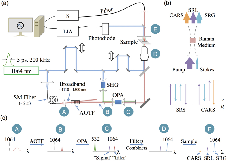
Figure 1.
(a) Schematics of the experimental setup. SHG: Second Harmonic Generation; OPA: Optical Parametric Generation; AOTF: Acousto-Optical Tunable Filter; S: Spectrometer; LIA: Lock-In Amplifier; (b) Illustration of energy transfer in SRS and CARS effects. SRG: stimulated Raman gain; SRL: stimulated Raman loss; ν: vibrational state; g: ground state; (c) The spectrum in each stage on the optical beam path.

