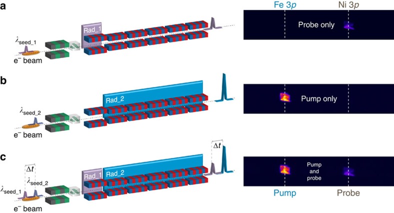
Figure 3. FEL source configuration and scattering data recording.
Diffracted intensity from the 20-nm-thick permalloy grating sample at 46.3° incidence. Data are collected under different seeding conditions (schematics on the left) using a position-sensitive CCD detector (images on the right); the 1,025 × 202 pixel images correspond to 13.84 × 2.73 mm2 and cover ∼1.48° in scattering angle. (a) The λseed_1=261.5 nm laser pulse is sent through the modulator, turning on the Ni-3p resonant FEL emission at λFEL_1=18.7 nm in Rad_1 (14th harmonic) and no emission from Rad_2. (b) The λseed_2=255 nm laser pulse generates the Fe-3p resonant FEL emission at λFEL_2=23.2 nm in the radiator section Rad_2 (11th harmonic) and no emission from Rad_1. (c) Both seed laser pulses, delayed by Δt, interact with the electron bunch, generating Fe-3p resonant pump and Ni-3p resonant probe FEL pulses, also delayed by Δt.

