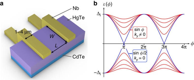
Figure 1. Geometry of the Josephson junction and predicted Andreev spectrum.
(a) Artist view of the Josephson junction. Mesa stripes of HgTe (represented in mauve) are patterned on the CdTe substrate (blue), with a width W=2 μm. Nb contacts (in yellow) are added at the surface, with a width of 1–4 μm, separated by a variable distance L. (b) Typical energy spectra ɛ(φ) of the Andreev bound states in a 3D TI-based junction, as a function of the phase difference φ in the JJ, with Δi. The gapless 4π-periodic topological mode is depicted as a blue line, corresponding to transverse momentum ky=0 and contributing to the 4π-periodic supercurrent I4π sin φ/2. Gapped modes depicted in red correspond to ky≠0 and contribute to the 2π-periodic supercurrent I2π (containing sin φ and higher order harmonics).

