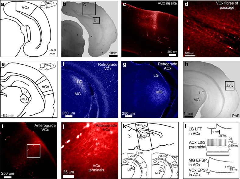
Figure 6. Direct functional projection from VCx to ACx.
(a) Diagram shows the stereological location of VCx in the coronal plane and sagittal plane (insert, top right). VCx, visual cortex. (b) A low-magnification bright-field micrograph of a coronal slice containing the VCx injection site; scale bar, 1 mm. (c) VCx injection site; scale bar, 250 μm. (d) Fluororuby labelled fibres of passage from VCx; scale bar, 100 μm. (e) Diagram shows stereological locations of the LG, MG and ACx in the coronal plane and sagittal plane (insert, top right). ACx, auditory cortex; LG, lateral geniculate; MG, medial geniculate. (f) Fluorescent labelling of LG following injection of retrograde tracer (Fluorogold) into VCx; scale bar, 250 μm. (g) Fluorescent labelling of MG following injection of retrograde tracer into ACx; scale bar, 250 μm. (h) A low-magnification bright-field micrograph showing the general location at which anterograde labelled fibres from VCx were found; scale bar, 1 mm. (i,j) Fluorescent micrographs (× 20, × 40) showing labelled synaptic terminals in ACx layer 2/3 after injection of anterograde tracer (Fluororuby) into VCx; scale bar, 250 μm and 25 μm. (k) Sagittal plane diagram shows the location of the peri-coronal slice preparation used to assess functional connectivity between VCx and ACx. Local field potentials evoked by LG stimulation were used to indentify putative VCx (bottom left). Stimulating electrodes were placed in putative VCx and in MG, to evoke responses in ACx (bottom right). (l) An LG-evoked local field potential recorded in VCx (top). Current-evoked responses in an ACx layer 2/3 pyramidal neuron (middle). MG-evoked EPSP verified that the neuron was auditory recipient and a VCx-evoked EPSP was obtained in the same neuron (bottom).

