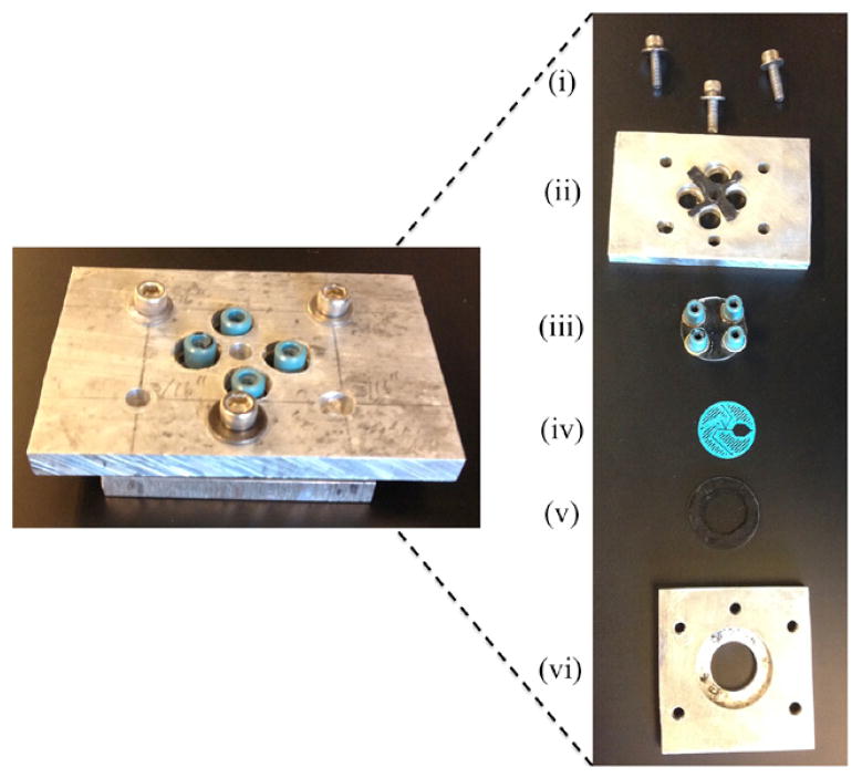
Figure 2.
The left image is the assembled mixer without the tubing connected. In the right image, each part of the mixer assembly is shown individually. (i) Screws that hold the mixer together. (ii) Top aluminum casing piece along with a rubber protective cushion between the aluminum plate and top window. (iii) Top window with Nanoport connections fastened permanently to the window, directly over the through holes drilled in the window for liquid transport. (iv) 3D printed mixer spacer that is sandwiched between the transparent windows. (v) Bottom transparent window along with a rubber cushion. (vi) Bottom aluminum plate with a counter-sunk hole to hold mixer in place.

