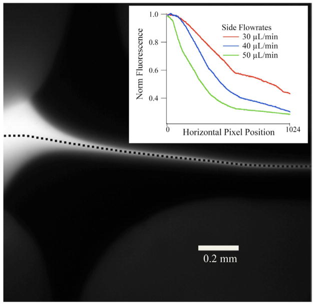
Figure 8.
The same cross mixer as figure 6, applied to another probe technique. In figure 6, the cross mixer was used with an infrared spectroscopy probe. Here, the cross mixer is applied to fluorescence spectroscopy with the same fluorescein sample as in figure 4. The fluorescein is flowing at 3 μL min−1 and is hydrodynamically focused by the side flows. Inset, fluorescence intensity normalized to the maximum intensity along the dashed line of the jet (in main image), with respect to the horizontal (left to right) pixel position of the camera for three separate KI side flow rates.

