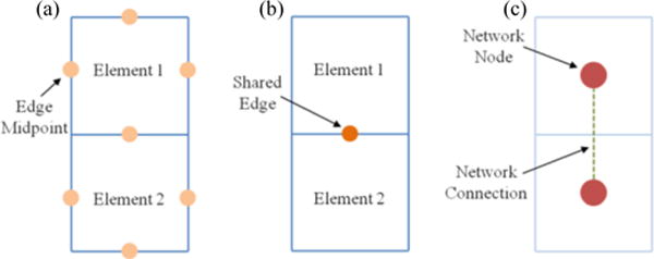
Fig. 1.

(a) Schematic showing two finite elements indicating the midpoint of each element edge. A deformation gradient tensor was determined for every edge midpoint within the finite element (FE) mesh. (b) Schematic showing two finite elements indicating their shared edge. A deformation gradient jump was calculated for every shared edge. (c) Schematic showing two finite elements and indicating how the FE mesh geometry is converted into a network. The deformation gradient jump was utilized when weighting the network connection.
