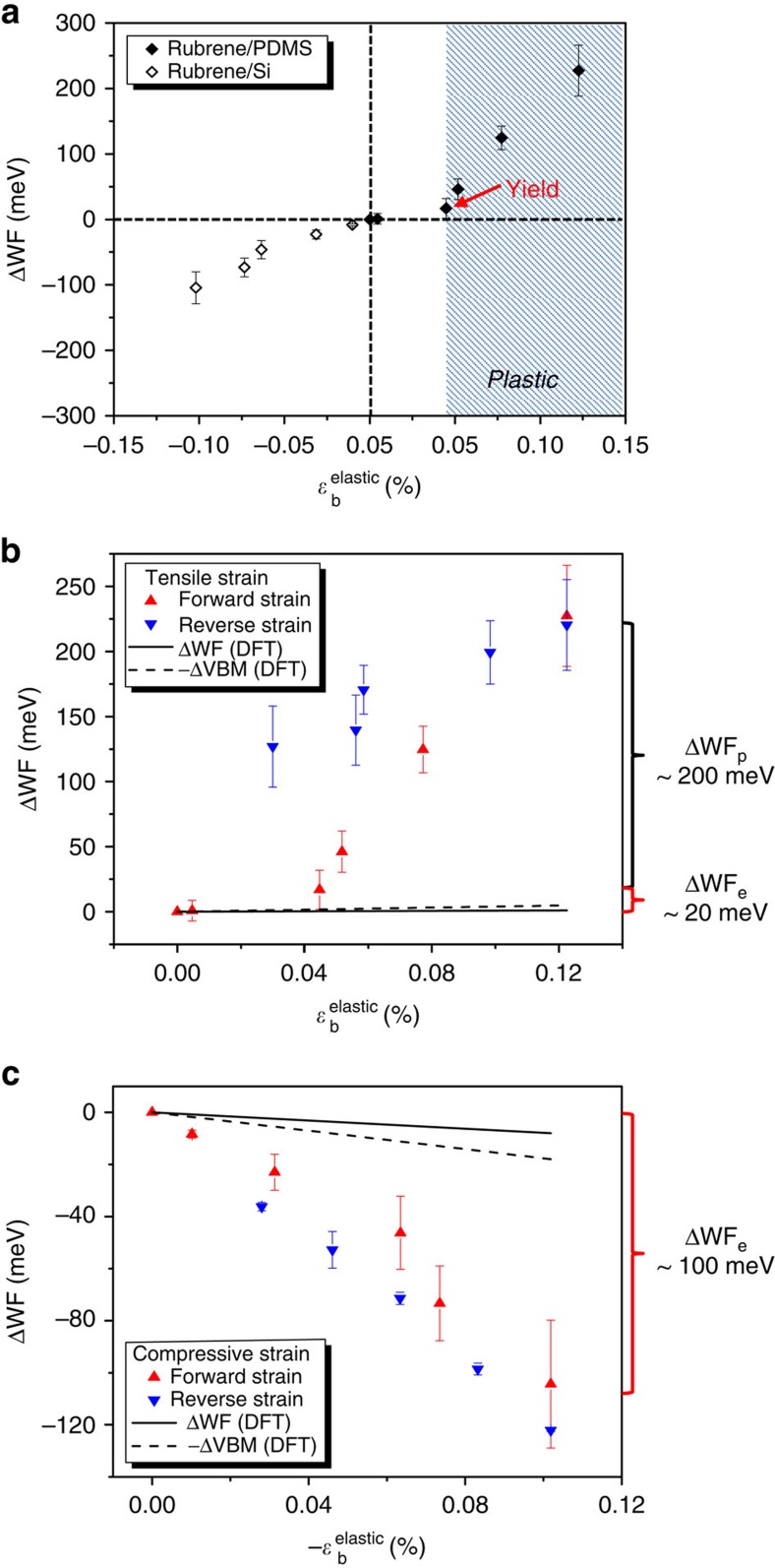
Figure 5. ΔWF as a function of substrate-induced elastic strain.
(a) ΔWF as a function of ɛelastic (tensile and compressive strain) along the b axis. The WF increases with tensile strain and decreases with compressive strain. Note that ΔWF in the shaded region is mainly a result of plastic deformation instead of elastic tensile strain. (b) ΔWF as a function of elastic tensile strain for forward and reverse strains. There is an elastic-to-plastic transition characterized by a sudden rise in ΔWF with strain. There is a large hysteresis of ΔWF between the forward and reverse tensile strains, indicating the effect of plastic deformation. The DFT calculation results are shown by the dashed line (−ΔVBM) and the solid line (ΔWF). The calculated −ΔVBM and ΔWF slightly increase with elastic tensile strain, a trend that qualitatively agrees with the experimental results. The quantitative disagreement between the calculations and the experimental results in the high-strain regime is attributed to plastic deformation, which is not considered in the calculations. (c) ΔWF as a function of elastic compressive strain for forward and reverse strains. The WF decreases with strain smoothly and no apparent elastic-to-plastic transition is observed. There is negligible hysteresis of ΔWF between the forward and reverse strains. The DFT calculation results are shown by the dashed line (−ΔVBM) and the solid line (ΔWF). The calculated −ΔVBM and ΔWF decrease with elastic compressive strain, a trend that qualitatively agrees with the experimental results. The deviation in the ΔWF magnitude of the calculations from the experiments may be due to dynamic effects that are not considered in the theoretical approach. The errors bars in ΔWF were based on standard deviation errors as described in Fig. 4.

