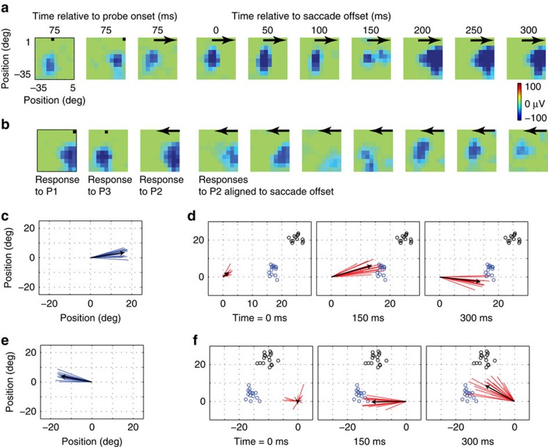
Figure 6. Remapping of LFP receptive fields.
(a) LFP receptive field of an example electrode for probes flashed during fixation (left two panels; fixation points indicated by black dot) and those flashed immediately before an away saccade, indicated by black arrows (third panel: responses aligned to probe onset; fourth panel and onwards: responses aligned to saccade offset). (b) LFP receptive field of an example electrode for towards saccades. (c) True LFP RF shift vectors of the population of 14 electrode sites with eccentricity >20°. (d) Remapping vectors of the same population at different times relative to saccade offset. The black arrows indicate average vectors. Since all the RFs are centred at the origin, saccade target positions vary (indicated by small black circles). Each vector's expected FF location (based on P3 RF) is indicated by small blue circle. (e) and (f) show the results from the same analysis as c and d for towards saccade. LFP, local field potential.

