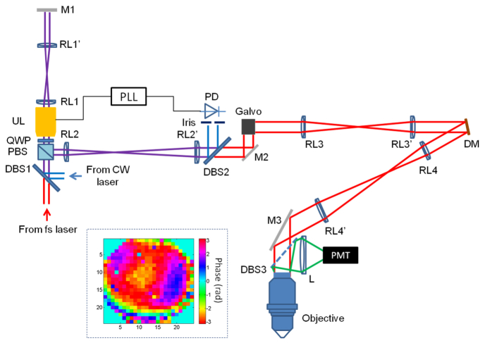
Fig. 1.
Diagram of the experimental setup. DBS: dichroic beam splitter, PBS: polarization beam splitter, QWP: quarter wave plate, UL: ultrasound lens, RL: relay lens, M: mirror, PLL: phase-lock loop, PD: photodetector, DM: deformable mirror, L: lens, PMT: photomultiplier tube. The inset: phase pattern for correcting the system aberration.

