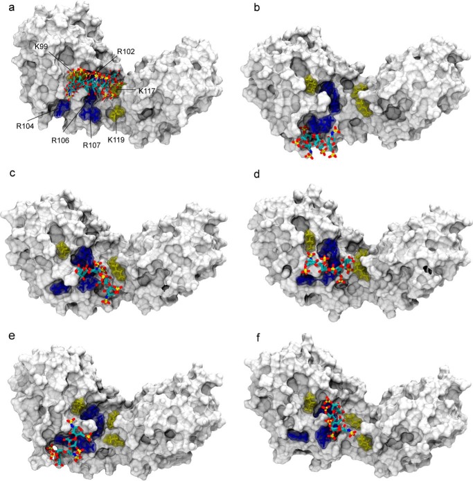
FIGURE 8.
Structural model of the heparin·IL-10 complex as obtained by PCS-based rigid body docking and subsequent MD simulation. a, ensemble of the five lowest energy structures of the 1C4 heparin ligand after PCS-based docking. The IL-10 molecule is represented with its van der Waals surface. Heparin is drawn in sticks and colored according to the atom type: carbon (cyan), oxygen (red), nitrogen (blue), and sulfur (gold). For clarity, only one heparin binding site is shown. For the second IL-10 dimer subunit on the opposite side of the central crevice, an identical docking pose was obtained, which involves the same group of basic residues. The best five docking solutions were used as the starting point for independent MD simulations from which snapshots after 105 ns are shown here (b–f). In the docking structure and during MD, the ligand position coincides with a cluster of positively charged amino acid residues of IL-10 as shown in sticks: arginines 102, 104, 106, and 107 are colored in blue, and lysines 99, 117, and 119 are shown in yellow.

