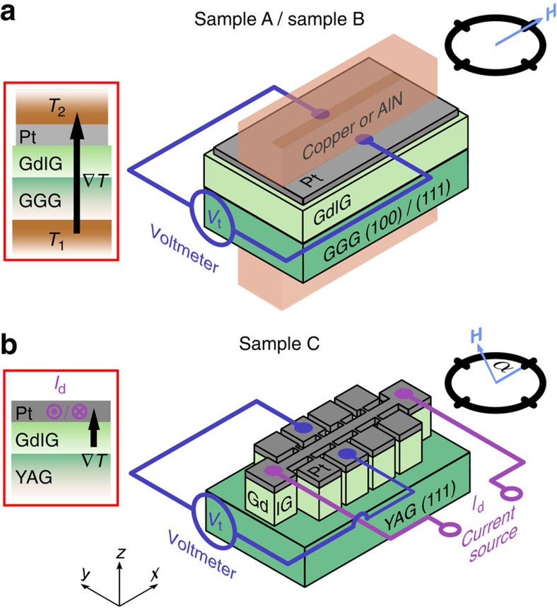
Figure 2. Experimental set-up.
(a,b) Sketches of the experimental configurations used to record the longitudinal spin Seebeck effect (SSE). Three different samples were investigated: Sample A and sample B consist of a GdIG(100 nm)/Pt(8 nm) and a GdIG(1 μm)/Pt(10 nm) bilayer fabricated on a (100)- and a (111)-oriented gadolinium gallium garnet (Gd3Ga5O12, GGG) substrate, respectively. Sample C is composed of a GdIG(26 nm)/Pt(10 nm) bilayer fabricated on a (111)-oriented yttrium aluminium garnet (Y3Al5O12, YAG) substrate. For sample A and B, the longitudinal SSE signal is determined by measuring the transverse voltage Vt perpendicular to an external magnetic field while modifying the magnetic field magnitude at a fixed magnetic field orientation  . The temperature gradient required for SSE measurements is generated by two independently heated copper blocks or AlN ceramics, respectively. The longitudinal SSE signal of sample C is obtained by recording Vt as a function of the in-plane orientation of the external magnetic field α at a fixed magnetic field magnitude of 2 T. Here the temperature gradient across the GdIG/Pt interface is generated by driving a large current Id along the Pt microstructure. The temperature-dependent resistance of the Pt is exploited for on-chip thermometry.

