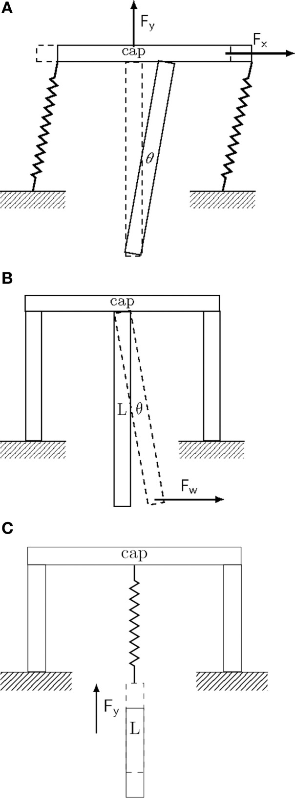
Figure 1.
Conceptual drawing of different implant fixation configurations. Drawings represent extreme and idealized cases of implant fixation to the skull (marked as ground). (A) Tethered fixation with semi-flexible attachment. The extent of XY-displacement is controlled by the semi-rigid attachment joints. Brain micromotion and body movements result in displacements predominantly in the upper part of the implant along all three spatial directions. Maximal displacement and pressure is attained about the entry point of the implant in the brain (see for example Welkenhuysen et al., 2011). (B) Rigid fixation mode. Brain micromotion caused by cardiovascular activity results in displacements predominantly in the lower part of the implant along all three spatial directions. (C) Non-tethered fixation mode. Motions of the body result in free displacement about the X and Y-axes, while the displacement in the Z-axis is controlled by the spring constant of the attachment joint.

