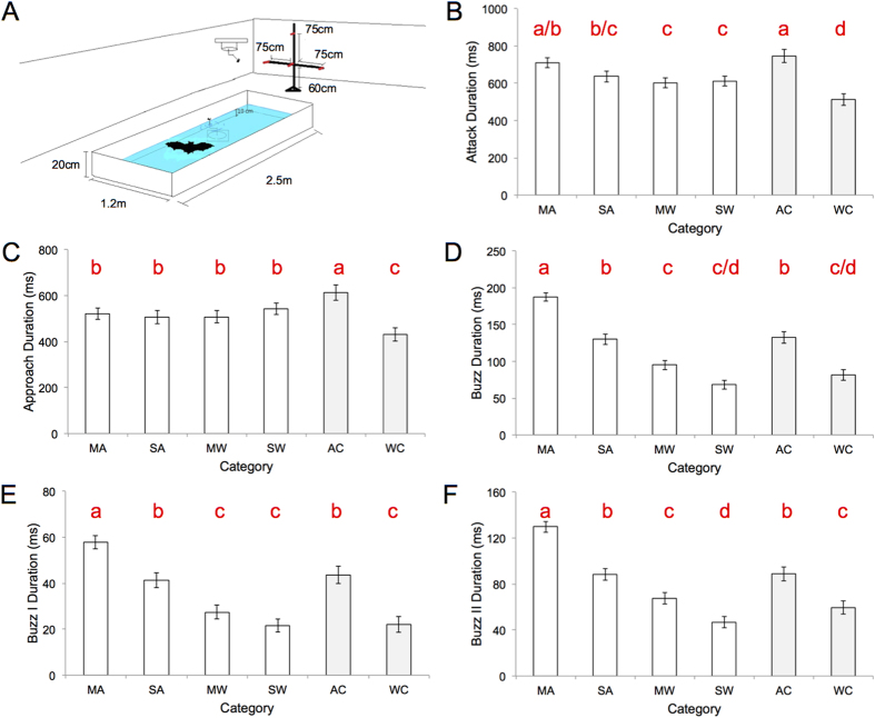
Figure 1. Flight room schematic and average (±SD) attack phase durations for all conditions.
(A) Flight room arrangement: pond, tether, rotators, microphone array, (B) total attack duration, (C) approach duration, (D) total buzz duration, (E) buzz I duration, (F) buzz II duration. MA = moving air, SA = still air, MW = moving water, SW = still water, AC = air control, WC = water control. Bars that do not share the same red lower case letter are significantly different (Tukey HSD post-hoc comparisons).

