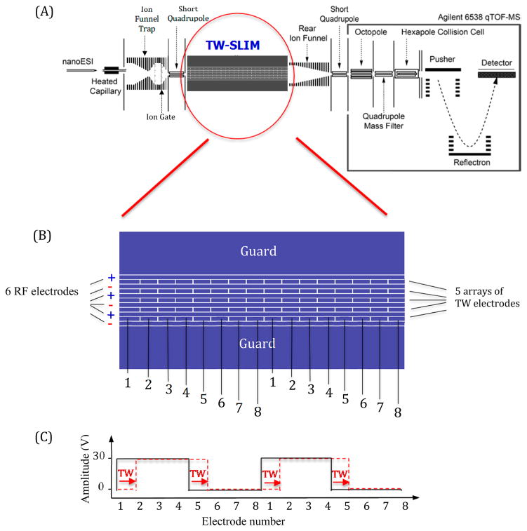
Figure 1.
(A) Schematic diagram of the instrumental arrangement. (B) Illustration of a portion of the 30 cm long TW-SLIM module showing the rf, traveling wave, and guard electrodes on one of the two PCB surfaces. The TW voltages are applied to subsets of eight electrodes numbered 1 through 8 forming a traveling wave. The sequence is repeated for the length of the module, on both surfaces. (C) The application of a 11110000 sequence to electrodes 1–8 is shown with the first step in the sequence indicated by the dashed red line (see text).

