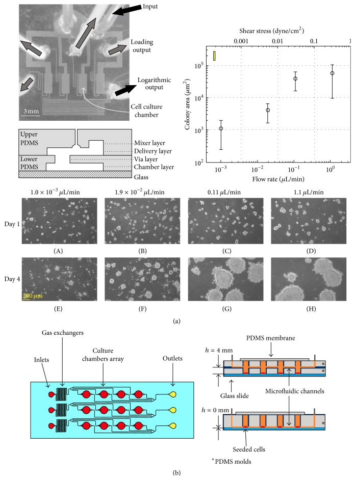
Figure 6.
(a) Photograph and schematic illustrate the shear generation device. The microchannel consisted of mixer, delivery, via, and chamber layers. The flow was delivered through inlet; each chamber had different flow rate (shear stress) because of different flow resistance which was induced by the geometry. The data analysis showed that ESC colony development was proportional to the shear stress level. (b) Schematic illustration of another shear generation microfluidic system with gas exchangers. The two types of channels (h = 0 mm, h = 4 mm) were used to create different shear stress levels. The result showed that the hESCs were more differentiated in high-shear (when h = 0 mm).

