Abstract
Purpose
Dynamic Contrast Enhanced MRI (DCE-MRI) was used to investigate the associations between intervertebral disc degeneration and changes in perfusion and diffusion in the disc endplates.
Methods
56 participants underwent MRI scans. Changes in DCE-MRI signal enhancement in the endplate regions were analyzed. Also, a group template was generated for the endplates and enhancement maps were registered to this template for group analysis.
Results
DCE-MRI enhancement changed significantly in cranial endplates with increased degeneration. A similar trend was observed for caudal endplates, but it was not significant. Group-averaged enhancement maps revealed major changes in spatial distribution of endplate perfusion and diffusion with increasing disc degeneration especially in peripheral endplate regions.
Conclusions
Increased enhancement in the endplate regions of degenerating discs might be an indication of ongoing damage in these tissues. Therefore, DCE-MRI could aid in understanding the pathophysiology of disc degeneration. Moreover, it could be used in the planning of novel treatments such as stem cell therapy.
Keywords: dynamic contrast enhanced magnetic resonance imaging, intervertebral disc endplate, intervertebral disc degeneration, lumbar spine
INTRODUCTION
Low back pain and its treatment is a major health problem associated with high costs, marginal outcomes and significant psychosocial and economic consequences. The majority of chronic back pain is associated with degeneration of the intervertebral discs (IVD), although the disc itself may not be the source of pain [1]. Despite extensive research on disc degeneration, there is still no consensus on the mechanisms of pathological degeneration or how it should be distinguished from normal aging processes. While the etiology of the pathologic degeneration process is still not completely understood, it has long been suspected that poor nutrient delivery to discs is a factor in the pathogenesis of IVD degeneration [2–4].
In adults, the IVD is avascular and the disc cells mainly rely on exchange of gas and solutes from the capillaries in adjacent subchondral bone (SB) [5–7]. Nutrients released from this capillary network diffuse across the cartilaginous endplate (CEP) region and eventually reach the disc cells in the nucleus pulposus (NP). It is suggested that factors such as mechanical failure or calcification of CEPs disrupt this transport mechanism and impact the viability of the disc cells and eventually lead to disc degeneration [5, 8–13]. Furthermore, the structural integrity of the SB - CEP interface is also critical for maintaining proper disc hydration. Defective endplates would lead to dehydration, loss of matrix proteins and structural failure of the discs [14].
Therefore, investigating perfusion through the capillary network in the SB and diffusion through the CEP region is critical to understand the endplate defects that manifest as a result of disc degeneration. Furthermore, such techniques might also aid emerging new therapies such as stem cell injections [15]. Such therapies assume that the disc degeneration is a result of compromised cellular activity and implanted cells would restore normal disc functions. However, implanted cells require functional endplates so that they could receive nutrients and remain viable. Therefore, it is necessary to verify proper functioning of SB - CEP interface before such therapies are attempted.
Diffusion through the endplate pathway was initially studied in vivo by various modalities including hydrogen wash-out measurements [16], radioactive tracers [17] and fluorescent tracers [14]. In vivo human studies were also conducted using Contrast Enhanced MRI, demonstrating changes in SB perfusion and CEP diffusion associated with disc degeneration [18, 19]. However, those studies required one pre-contrast image and several follow-up image acquisitions at delayed intervals for up to 6 hours [19] or 24 hours [18]. Although those investigations provided invaluable information, the approach is not practical due to very long time commitment required by the participants. Furthermore, they required two to three times the recommended dose of the contrast agent, which could increase the risk of side effects. A recent study utilized a feasible DCE-MRI acquisition with approximately 13 minutes of data acquisition and used the recommended dosage (0.1 mmol/kg) of contrast agent. The results demonstrated significant changes in signal enhancement time course in the SB and CEP regions of degenerating discs [20]. However, the cohort was relatively small in that study, which limited the generalization of the findings to the broader population. Moreover, that study reported only the temporal characteristic of the average signal in the SB and CEP regions.
The goal of the study presented here is to utilize DCE-MRI to investigate spatiotemporal characteristics of perfusion and diffusion in the SB and CEP regions of healthy and degenerating discs. Our study complements those earlier studies by reporting spatial distribution of DCE-MRI enhancement over the surface of SB and CEP regions. Our findings demonstrate evidence of major changes in the vascular and extravascular space in the SB and CEP regions over the course of degeneration. These findings might help us understand aberrant changes in these regions that are critical for spinal health.
METHODS
Study group
This study was approved by the Institutional Review Board and written consents were obtained from 62 adult participants. The subjects were asked to avoid any heavy physical activity prior to their scan and they rested on a stretcher for 30 minutes prior to scan. This helped reduce variations in disc physiology due to variations in daily loading of the discs. The scans were conducted in the morning or early in the afternoon. 19 participants had a history of low back pain and the rest of the participants were asymptomatic. The subjects were interviewed and their medical charts were reviewed (if available) and those with disc herniation, metabolic bone disease, any surgery or trauma in lumbar level, osteoporosis, spondylolisthesis, malignancy, morbid obesity, renal or major cardiovascular diseases were excluded in this study. MRI data from 56 participants were utilized for this report. The remaining 6 participants could not complete the study due to problems stemming from scanner failures (N=5) or contrast administration (N=1). The demographic information of the 56 participants is given in Table 1.
Table 1.
Demographic characteristics of the study group
|
|
|
||||
|---|---|---|---|---|---|
| Age (year) | Height (m) | Weight (kg) | BMI (kg/m2) | N | |
|
|
|
||||
| Median [min-max] | 36.5[20–57] | 1.73[1.55–1.93] | 76[51–113] | 26.5[18.1–41.6] | Female 24 |
| Mean±SD | 36.3±11.2 | 1.72±0.10 | 78.2±15.3 | 26.3±4.6 | Male 32 |
|
|
|
||||
MRI protocol
Images were acquired using a 3T GE Discovery MR750 MRI system (GE Healthcare, Waukesha, WI USA). All images were acquired using a CTL-spine coil with a FOV=310mm. A conventional T2 weighted (T2W) MRI was acquired using a Fast Spin-Echo sequence with TR=4500ms, TE=104ms, ETL=24, 1mm in-plane resolution and 16-sagittal slices with 3mm thickness. DCE-MRI data were acquired using a 3D dual-echo FSPGR with Dixon’s fat/water separation method. The acquisition parameters were: TR=4.0ms, TE1=1.1ms, TE2=2.2ms, flip-angle=12°, acquisition matrix=310×300 (interpolated to 0.61mm in-plane resolution), 8-sagittal slices, 6mm thick (which was interpolated to 3mm). The contrast (Gd-DTPA 0.1 mmol/kg) was administered manually as a bolus via an antecubital vein at the end of the 2nd dynamic frame. 23 frames were acquired with 28s frame rate and 8s delay between 2nd and 3rd frames, resulting in a total data acquisition time of about 10 minutes, 56 seconds.
T2W MR images were reviewed by two expert radiologists and a trained research assistant for Pfirrmann classification of the lumbar IVDs [21]. If there was a disagreement between the raters, the median score was assigned to the disc.
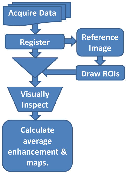
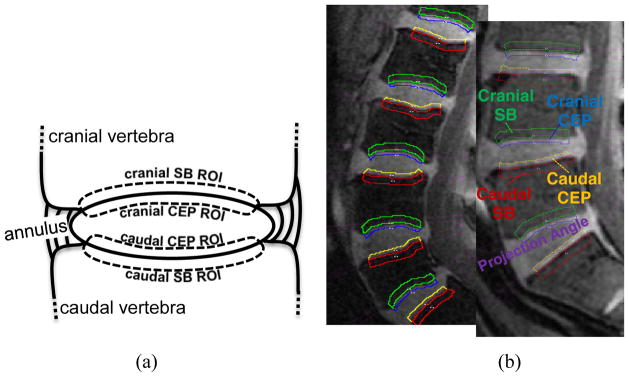
The data was processed as shown in the pipeline illustrated in Fig. 1. Before analysis, motion correction was performed on each DCE-MRI image series using 12-parameter affine transformation followed by nonlinear registration using FSL software tools (http://fsl.fmrib.ox.ac.uk/fsl/fslwiki/). Then, a trained operator manually drew regions of interest (ROI) on every slice of pre-contrast images of the DCE-MRI to segment out the 10 CEPs and SBs in the lumbar area (Fig. 2). We followed the guidelines described in previously published articles to outline those regions [18, 20]. ROI drawings were done on pre-contrast DCE-MRI images because the CEPs with short T2 relaxation remain visible in this particular pulse sequence with short TE. Therefore, these images provided more accurate delineation of the CEP regions, which would not be the case with conventional T1 or T2 weighted MRI images.
Fig. 1.
Flow diagram of data processing pipeline.
Fig. 2.
(a) Schematic diagram of IVD and adjacent vertebral bodies and ROIs. ROIs were named according to their positions relative to the adjacent IVD. (b) ROIs and corresponding projection planes (magenta straight lines) are shown for two different subjects. Note the subject-to-subject variations in the geometry of endplate surfaces
Intra-observer consistency was tested by having the operator repeat the ROI drawings on a subset of the data. He was not informed about those repeated drawings and he was blinded to the identities of the subjects. The repeated drawings had, on average, 93% overlap in the NP and 82% in the CEPs and SBs. The ROIs were inspected by a second researcher (VEA). If there were disagreements, the two operators discussed and finalized the ROI. The terms cranial and caudal were used in naming the SB and CEP ROIs to describe the position of the ROI relative to the corresponding IVD.
Average enhancement in ROIs and statistical analysis
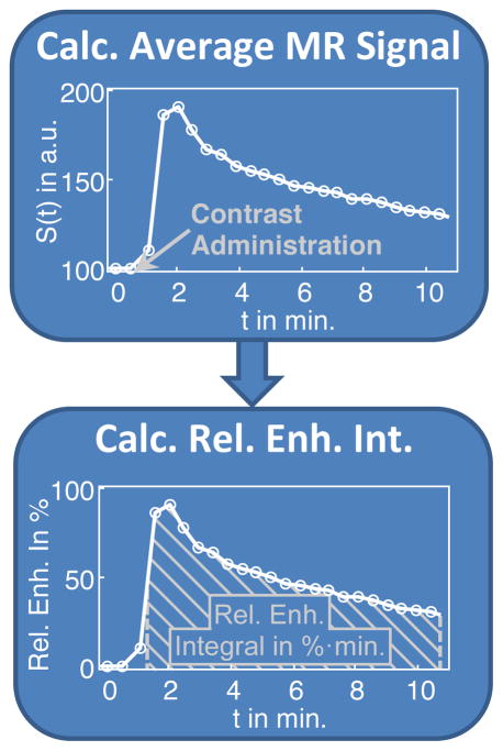
Volume-averaged signal enhancement time course was calculated in each ROI for statistical analysis. The average of the two pre-contrast time points was used as baseline and relative percentage enhancement time courses were calculated with respect to the baseline (Fig. 3). Then, the integral along the time course was calculated from 1.7 min (0.7 min. after contrast administration) to 10.9 min (the end of data acquisition). The unit for this integral is percentage enhancement multiplied by minutes (%·min). From here on, the term DCE-MRI enhancement refers to this integral.
Fig. 3.
Average MR signal within the ROI was converted to percent enhancement and the integral of the enhancement curve was calculated.
Statistical tests were performed using SAS 9.4 (SAS Institute, Cary, NC USA) to analyze the associations between disc degeneration and DCE-MRI enhancement. Age, body mass index (BMI) and sex were also used as covariates. The statistical significance (alpha) level of 0.05 was used. A proportional-odds cumulative logit model was applied to fit the data. Within subject variances were also taken into account in this model. This model estimates the increase in odds of reaching into or over any category of disc grade (I – IV), associated with one-unit or one-level increase in the covariate, holding all other covariates constant.
Spatial maps of DCE-MRI enhancement in SB and CEP regions
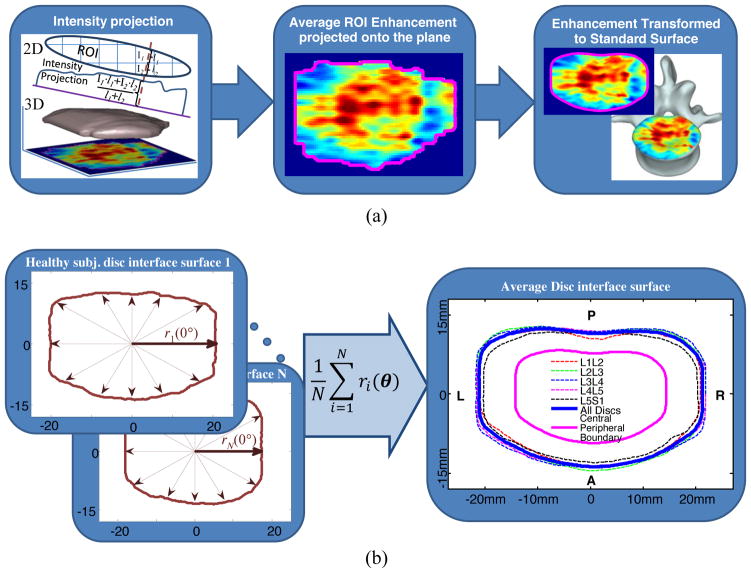
In order to generate spatial maps of DCE-MRI enhancement, the curved surfaces should be first projected onto a planar surface. The projection plane for each vertebral body surface was estimated by calculating the first and the second moments of the corresponding ROI. Using these moments, ROI’s center of mass and axis of orientation, which was defined as the direction of the axis with least inertia, were calculated [22]. Using these orientations, planes parallel to the cranial and caudal surfaces of each lumbar IVD were determined. A representative sagittal slice with projection planes (magenta line) is shown in Fig. 2(b). Then, the DCE-MRI enhancement of each voxel within a ROI was calculated and projected onto the corresponding plane for each CEP and SB. Projections were calculated along the lines perpendicular to the surface (Fig. 4(a)). The length of the projection through each voxel is taken into account for proper normalization. All calculations were done using in-house code in Matlab (Mathworks, Natick, MA USA).
Fig. 4.
(a) Projection of voxel enhancement values onto a caudal plane and registration onto the template surface and mapping onto a representative vertebral body. (b) Schematic illustration of template surface generation using individual ROIs from healthy discs. The central region is shown with the magenta line and the peripheral region is the area between the magenta and the blue lines.
In order to illustrate typical changes in spatial distribution of DCE-MRI enhancement with disc degeneration, one needs to average, for instance, all SB and CEP enhancement maps of grade IV discs. This requires that the anatomic variations between subjects as well as variations across all lumbar levels should be taken into account. Therefore, we generated a template of the surface between the disc and the vertebral body and spatially normalized each individual CEP and SB surface projections onto this template. The template was generated from the SB and CEP ROIs of subjects with healthy discs (Grades I or II across all lumbar levels). Overall, data from 21 subjects were used for the template (Age: 30±9y; 9 Females; Height: 171±10cm; Weight: 71±12kg, BMI: 24.3±3.7kg/m2). To generate this group template, first the center of mass was estimated for each individual surface. Then, the distance from the center of mass to the edge of the surface was calculated along radial lines with 1° increments (Fig. 4(b)). First, this was done for each lumbar level separately (dotted lines in Fig. 4(b)) and then these templates were averaged using the same process to obtain one single template (blue solid line in Fig. 4(b)). Then, each CEP and SB enhancement map was spatially registered to this template as shown in Fig. 4(a).
Once normalized, the enhancement maps of the CEPs and SBs were grouped according to the Pfirrmann classification of corresponding disc and averaged to demonstrate spatial enhancement characteristics for discs with different levels of degeneration (grades I and II discs were considered healthy and grouped together for illustrations).
We further separated the SB and CEP ROIs into central and peripheral regions to study the different enhancement characteristics we have seen in these regions. The area between the blue and magenta lines in Fig. 4(b) is defined as the peripheral region (54% of the total surface area), and the area inside the magenta line is the central region (46% of the total surface area). The boundary is defined heuristically based on the spatial enhancement characteristic seen in healthy endplates.
RESULTS
Average DCE-MRI enhancement in SB and CEP regions
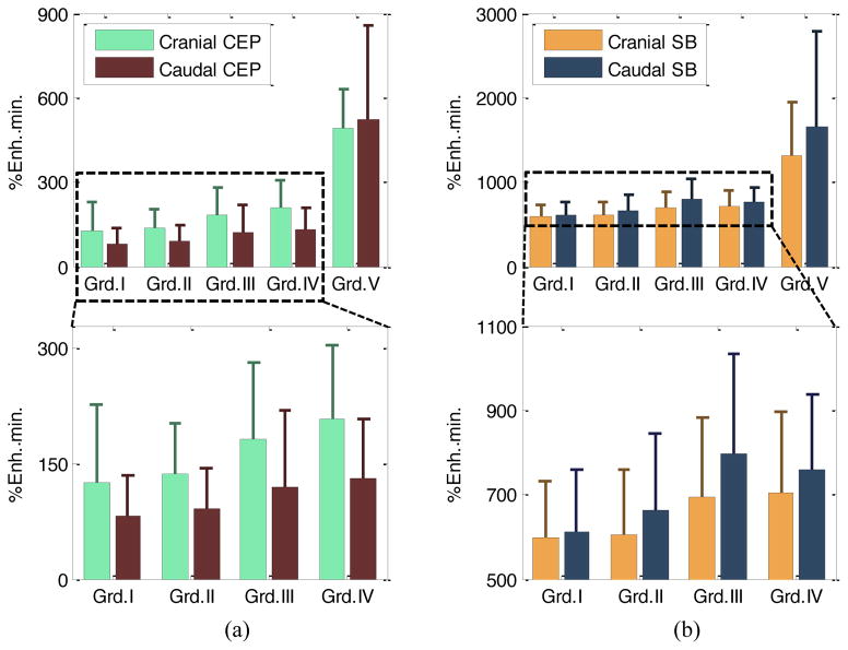
Summary of Pfirrmann grade distribution in the lumbar IVDs of our cohort is given in Table 2. Grade V discs were not used for statistical analysis because there were relatively small number of Grade V IVDs (N=6). In addition, their enhancement values were substantially higher than grades I – IV, which would have skewed the statistical outcomes (Fig. 5). Besides, Grade V represents severe degeneration, so changes from Grade I through IV would be clinically more interesting. Fig. 5 illustrates the mean and standard deviation of DCE-MRI enhancement for CEP and SB regions for Pfirrmann grades I through V.
Table 2.
Number of discs in each grade according to the Pfirrmann classification
| Grade I | Grade II | Grade III | Grade IV | Grade V | |
|---|---|---|---|---|---|
| Number of Discs | 13 | 177 | 51 | 33 | 6 |
Fig. 5.
Mean and standard deviation of DCE-MRI enhancement for CEP ROIs (a), and SB ROIs (b) for Pfirrmann grades I to V (top panels). To illustrate changes from Grade I to IV in better detail, data from Grade V discs were excluded, and shown in the plots below. The range for y-axis for the SB regions was set between 500 and 1100 to show the dynamic range better. Note that different y-axis scales were used for CEP and SB regions because avascular CEPs have lower Gd-DTPA concentrations through diffusion.
Table 3 summarizes the results of the statistical analysis, testing the associations between disc degeneration and DCE-MRI enhancement in regions of interest. Age, sex, and BMI were also included as covariates in the statistical model. Note that each variable was scaled such that all variables span similar ranges. This prevents the statistical estimations being overwhelmed by a large variable. The analysis showed that Cranial CEP enhancement has a statistically significant association with disc degeneration grade (p=0.0161). In other words, an increase in Cranial CEP enhancement increases the probability of the corresponding disc having a higher degeneration grade, given that all other variables in the model kept constant.
Table 3.
Results of analysis using the proportional-odds cumulative logit model for sex, age, BMI and enhancements in CEP and SB regions. Grade V discs were excluded in this analysis. The estimated coefficients (EST) correspond to the increase in odds of reaching into or over any disc degeneration grade with respect to one-level or one-unit increase in covariates while holding all the other covariates constant
| Variable | Level | EST (95CI) | P value |
|---|---|---|---|
| sex | F vs. M | 0.90(0.37,2.19) | 0.8109 |
| age | Year | 1.11(1.08,1.15) | <.0001 |
| BMI | kg/m2 | 1.05(0.97,1.14) | 0.2136 |
| Cranial SB Enh. | Cranial SB Enh./100 | 0.87(0.60,1.24) | 0.4308 |
| Cranial CEP Enh. | Cranial CEP Enh./100 | 2.01(1.14,3.55) | 0.0161 |
| Caudal CEP Enh. | Caudal CEP Enh./100 | 1.75(0.96,3.19) | 0.0662 |
| Caudal SB Enh. | Caudal SB Enh./100 | 1.00(0.80,1.25) | 0.9973 |
There was also a noticeable difference between the cranial and caudal SB and CEP enhancements. ANOVA test (with grade V excluded) showed that this difference increased significantly with degeneration in the SB regions (p=0.01) but not in CEPs. Within a single grade, this difference was significant for both SB and CEP regions for grades II through IV (p<0.001), but not for grades I and V. It is possible that the small number of discs with grades I and IV did not have enough statistical power.
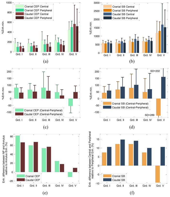
Average enhancement values in peripheral and central regions of the SB and CEP ROIs are plotted in Fig 6(a, b). Additionally, the enhancement differences (central - peripheral) are plotted in Fig. 6(c, d). Fig. 6(e, f) shows plots of differential enhancement with respect to periphery { }. It can be seen that the enhancement in the central region increases more than the periphery in the SB during early stages of degeneration, but then an increase in enhancement is seen in the peripheral regions. In the CEP regions, however, the relative enhancements remain similar in early stages (with an increase in variability in grade III discs) and a noticeable drop in relative ratios is seen with further increase in degeneration.
Fig. 6.
Bar graphs of DCE-MRI enhancement for central and peripheral regions in CEP ROIs (a), and subchondral bone (SB) ROIs (b) for Pfirrmann grades I to V were shown. Note that different y-axis scales were used for CEP and SB regions. Enhancement differences (central-peripheral) were given in (c) and (d). In (e, f) mean enhancement difference (central-peripheral) relative to peripheral enhancement is shown.
The same proportional-odds cumulative logit model applied to these sub-regions showed that the enhancements in the peripheral region of cranial and caudal CEPs were significantly associated with degeneration (p=0.0235 and p=0.005, respectively). Age was again a significant factor (p<0.0001).
Spatial characteristics of DCE-MRI enhancement and changes with disc degeneration
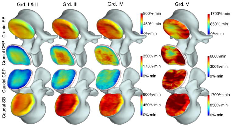
Group-averaged enhancement maps in the CEPs and SBs are shown in Fig. 7. Each column shows enhancement maps grouped by the degeneration grade of the adjacent disc. SB enhancement maps are overlaid onto the template vertebral body and enhancement in cranial and caudal CEPs were shown as two separate surfaces between the two vertebral bodies (NP removed). There were 190 healthy (grades I and II), 51 grade III, 33 grade IV and 6 grade V discs. Different scales had to be used for color maps in CEPs and adjacent SBs in this graph because of the large difference in enhancement peaks between those two regions.
Fig. 7.
Voxelwise enhancement maps in CEP and SB ROIs projected and transformed onto the template as described in Fig. 4. Enhancement maps were grouped according to the degeneration grade of the corresponding disc and averaged to generate these maps. Color bars are included next to the plots to describe colors used in these maps. Different scales were used for CEP and SB regions. Also note that CEP and SB regions around Grade V discs had substantially elevated enhancement, therefore the scales had to be almost doubled to capture the increased dynamic range.
DISCUSSION AND CONCLUSION
The findings in this study demonstrate profound changes in MRI contrast agent uptake in SB and CEP regions of degenerating discs. Both the average signal enhancement and the spatial distribution of enhancement differed significantly between discs with different degrees of degeneration. Although differences in average enhancement in similar ROIs were shown in earlier studies, our results demonstrate differences in spatial distribution of such enhancements using a group analysis. Furthermore, notable differences in enhancements between cranial and caudal regions were shown here.
Increased contrast agent concentration in these regions with increasing disc degeneration suggests increased perfusion in the SB and increased diffusion in the CEP regions. This could be partly attributed to increased micro-fractures and porosity in the SB adjacent to a degenerating disc [12, 23]. Increased porosity would allow more contrast agent to accumulate and boost the DCE-MRI signal enhancement. In addition, increase in DCE-MRI signal could also be mediated by increased vascularity. A recently published study reported angiogenesis in the SB regions of degenerating discs [24]. In another study, researchers induced angiogenesis in the SB of rabbits using nimodipine and investigated changes in contrast enhancement in the NP [25]. Interestingly, their study showed that the relationship between the SB microvasculature and solute transport into the NP was not straightforward. They did not find a clear correlation between SB vessel density and extent of diffusion. The evidence from those studies might explain the findings in our study, which seem to contradict earlier studies suggesting associations between poor nutrient delivery and disc degeneration. Besides, more porous SB would cause faster leakage of water and matrix molecules, possibly contributing to the disc degeneration.
A study published in 1996, which investigated the transport of solutes of different sizes in the CEP [14], also provides evidence that might help explain the DCE-MRI enhancement characteristics seen in the CEP regions. The contrast agent used in our study corresponds to the smaller molecular weight solutes tested in that study. Therefore, it is expected to enter the matrix to a greater extent. However, an interesting aspect of the contrast agent that we used was its ionic charge. Larger concentration of negatively charged proteoglycans (PG) in healthy CEPs would repel some of the Gd-DTPA molecules. However, loss of PGs in degenerating CEPs would allow more contrast agent to diffuse. This might explain significant increases in the CEPs as the discs degenerate. Higher concentrations of the contrast agent in the SBs combined with lower PG concentrations could lead to higher diffusion of the contrast agent in the CEP.
Another interesting finding in our study was the difference between cranial and caudal CEPs. Average enhancement in cranial CEPs was significantly different between discs with different grades (p=0.0161), whereas a similar trend was seen in the caudal CEPs, but it was not statistically significant (p=0.066). This effect can also be seen clearly in the spatial enhancement maps of Fig. 7. There is a visible increase in enhancement in the cranial CEPs while it is less pronounced in the caudal CEPs. This might be partly due to the fact that average enhancement was consistently lower in the caudal CEPs (Fig. 5.) across all degeneration grades and the rate of increase also appears to be lower. The reason for this discrepancy is not clear and we could not find any evidence from the literature to explain it. Further studies are needed to understand this difference. However, it is worth noting that if we analyze only the enhancements in the peripheral regions of the CEPs, both of the cranial and caudal sides show significant association with degeneration. Another striking finding was the opposite differential enhancements in SBs. Both average enhancement plots (Fig. 5) and spatial enhancement maps (Fig. 7) show that caudal SBs have higher enhancement than the cranial ones. This observation is in accord with earlier cadaver studies in which they demonstrated that the caudal SBs are thinner and more prone to fractures [26, 27], which might lead to increased leakage of contrast agent. However, it is not clear why the differential enhancement in caudal versus cranial SBs is the opposite of what is seen in CEPs. Differences in endplate permeability or endplate calcification might play a role in the results seen here. Additional studies are needed to understand these trends.
Fig. 6 and Fig. 7 also show that the central CEP regions had higher enhancement than the periphery in healthy discs. This is expected since the density of the capillary bed is higher near the NP. However, this typical distribution in healthy SBs and CEPs changed as the discs degenerated. In the extreme case of Grade V discs, the distribution became highly irregular.
In our analyses age, BMI and sex were also included as covariates. While age was a significant factor (p<0.0001), BMI was not significantly associated with degeneration. There were also no significant differences between males and females.
One of the caveats in this study is the partial volume effects in the selected ROIs. This is a limitation that exists for any ROI-based analysis on MR images such as those earlier contrast enhanced MRI studies [18, [19]. Even though the boundaries of the CEPs are clearly delineated in this acquisition with short TE, some of the voxels in the CEP ROI might have included portions of the NP. However, the contributions from the NP should be negligible since the diffusion of contrast agent into the NP during the 11-minute data acquisition should be very small [18]. Similarly, partial volume effects might have also influenced the SB enhancement characteristics, if some voxels included parts of the trabecular bone. However, we anticipate that the influence of the voxels with partial contributions from the trabecular bone would be minimal because of the higher density of capillaries in the SB region.
Relatively high variance in our data might have also influenced the significance of some of the tests. For instance, the caudal CEP enhancement shows a notable trend, but narrowly misses the p<0.05 threshold. While such variations might be due to anatomical differences between participants, it might also be due to the limited and qualitative nature of the Pfirrmann classification. This grading scheme classifies subjects only based on the appearance of discs in T2W images. First of all, there are occasional disagreements between raters about the grade of a disc. Additionally, two discs that might appear similar in a T2W image might be going through substantially different stages of morphological and physiological changes, which are not yet reflected in disc hydration. Our unpublished data showed that some discs with similar appearances in T2W images had significantly different diffusion (ADC), T1ρ and disc height loss values, which are all shown to be associated with disc degeneration. This is the main motivation behind our work to explore quantitative imaging techniques that directly probe physiology and morphology. Such measurements might complement Pfirrmann classification to assess the stage of the disc degeneration more accurately.
The findings in our study demonstrate that DCE-MRI is a novel approach to study changes in the SB and CEP with degeneration. It can be easily integrated into studies that investigate the etiology of disc degeneration. Other advanced imaging techniques such as UTE [4, 28] and T2* mapping [29] can also be incorporated into the protocol to obtain a more comprehensive assessment of endplate defects. New findings that emerge from such studies might help with the discovery of new treatment regimes. Moreover, it could be a critical tool for effective stem cell therapies. Current practice requires only conventional T1W and T2W MRI images for patients suffering from chronic low back pain. Quantitative and dynamic imaging techniques might have an important contribution for more effective management of patients suffering low back pain due to disc degeneration.
Acknowledgments
This study is supported in part by funds from Advancing a Healthier Wisconsin AHW28 FP00002161 and AOSpine Clinical Priority program. We would like to thank Adam Pfaller, Judeen Richeen and study participants for their help and participation on this study. We also would like to thank Aniko Szabo, Ph.D. and Qun Xiang, M.Sc. from the Division of Biostatistics, Institute for Health and Society at MCW for their assistance in statistical analyses. Their support is funded by the National Center for Advancing Translational Sciences, National Institutes of Health, through Grant Number 8UL1TR000055.
Footnotes
Ethics:
This study was approved by the Institutional Review Board of the Medical College of Wisconsin, Milwaukee, WI, where the study was conducted.
References
- 1.Luoma K, Riihimäki H, Luukkonen R, et al. Low back pain in relation to lumbar disc degeneration. Spine. 2000;25:487–492. doi: 10.1097/00007632-200002150-00016. [DOI] [PubMed] [Google Scholar]
- 2.Adams MA, Roughley PJ. What is intervertebral disc degeneration, and what causes it? Spine. 2006;31:2151–2161. doi: 10.1097/01.brs.0000231761.73859.2c. [DOI] [PubMed] [Google Scholar]
- 3.Rajasekaran S, Naresh-Babu J, Murugan S. Review of postcontrast MRI studies on diffusion of human lumbar discs. J Magn Reson Imaging. 2007;25:410–418. doi: 10.1002/jmri.20853. [DOI] [PubMed] [Google Scholar]
- 4.Moon SM, Yoder JH, Wright AC, et al. Evaluation of intervertebral disc cartilaginous endplate structure using magnetic resonance imaging. Eur Spine J Off Publ Eur Spine Soc Eur Spinal Deform Soc Eur Sect Cerv Spine Res Soc. 2013;22:1820–1828. doi: 10.1007/s00586-013-2798-1. [DOI] [PMC free article] [PubMed] [Google Scholar]
- 5.Boos N, Weissbach S, Rohrbach H, et al. Classification of age-related changes in lumbar intervertebral discs: 2002 Volvo Award in basic science. Spine. 2002;27:2631–2644. doi: 10.1097/01.BRS.0000035304.27153.5B. [DOI] [PubMed] [Google Scholar]
- 6.Bogduk N. Clinical Anatomy of the Lumbar Spine and Sacrum. Elsevier Health Sciences; 2005. [Google Scholar]
- 7.Rodriguez AG, Slichter CK, Acosta FL, et al. Human Disc Nucleus Properties and Vertebral Endplate Permeability. Spine. 2011;36:512–520. doi: 10.1097/BRS.0b013e3181f72b94. [DOI] [PMC free article] [PubMed] [Google Scholar]
- 8.Bibby SRS, Urban JPG. Effect of nutrient deprivation on the viability of intervertebral disc cells. Eur Spine J Off Publ Eur Spine Soc Eur Spinal Deform Soc Eur Sect Cerv Spine Res Soc. 2004;13:695–701. doi: 10.1007/s00586-003-0616-x. [DOI] [PMC free article] [PubMed] [Google Scholar]
- 9.Jackson AR, Huang C-Y, Gu WY. Effect of endplate calcification and mechanical deformation on the distribution of glucose in intervertebral disc: a 3-d finite element study. Comput Methods Biomech Biomed Engin. 2011;14:195–204. doi: 10.1080/10255842.2010.535815. [DOI] [PMC free article] [PubMed] [Google Scholar]
- 10.Nachemson A, Lewin T, Maroudas A, Freeman MA. In vitro diffusion of dye through the end-plates and the annulus fibrosus of human lumbar inter-vertebral discs. Acta Orthop Scand. 1970;41:589–607. doi: 10.3109/17453677008991550. [DOI] [PubMed] [Google Scholar]
- 11.Shirazi-Adl A, Taheri M, Urban JPG. Analysis of cell viability in intervertebral disc: Effect of endplate permeability on cell population. J Biomech. 2010;43:1330–1336. doi: 10.1016/j.jbiomech.2010.01.023. [DOI] [PubMed] [Google Scholar]
- 12.Ayotte DC, Ito K, Perren SM, Tepic S. Direction-dependent constriction flow in a poroelastic solid: the intervertebral disc valve. J Biomech Eng. 2000;122:587–593. doi: 10.1115/1.1319658. [DOI] [PubMed] [Google Scholar]
- 13.Hadjipavlou AG, Tzermiadianos MN, Bogduk N, Zindrick MR. The pathophysiology of disc degeneration A CRITICAL REVIEW. J Bone Joint Surg Br. 2008;90-B:1261–1270. doi: 10.1302/0301-620X.90B10.20910. [DOI] [PubMed] [Google Scholar]
- 14.Roberts S, Urban JPG, Evans H, Eisenstein SM. Transport Properties of the Human Cartilage Endplate in Relation to Its Composition and Calcification. [Miscellaneous Article] Spine Febr 151996. 1996;21:415–420. doi: 10.1097/00007632-199602150-00003. [DOI] [PubMed] [Google Scholar]
- 15.Huang Y-C, Urban JPG, Luk KDK. Intervertebral disc regeneration: do nutrients lead the way? Nat Rev Rheumatol. 2014;10:561–566. doi: 10.1038/nrrheum.2014.91. [DOI] [PubMed] [Google Scholar]
- 16.Ogata K, Whiteside LA. 1980 Volvo award winner in basic science. Nutritional pathways of the intervertebral disc. An experimental study using hydrogen washout technique. Spine. 1981;6:211–216. [PubMed] [Google Scholar]
- 17.Urban JP, Holm S, Maroudas A, Nachemson A. Nutrition of the intervertebral disc: effect of fluid flow on solute transport. Clin Orthop. 1982:296–302. [PubMed] [Google Scholar]
- 18.Rajasekaran S, Babu JN, Arun R, et al. ISSLS prize winner: A study of diffusion in human lumbar discs: a serial magnetic resonance imaging study documenting the influence of the endplate on diffusion in normal and degenerate discs. Spine. 2004;29:2654–2667. doi: 10.1097/01.brs.0000148014.15210.64. [DOI] [PubMed] [Google Scholar]
- 19.Tibiletti M, Galbusera F, Ciavarro C, Brayda-Bruno M. Is the Transport of a Gadolinium-Based Contrast Agent Decreased in a Degenerated or Aged Disc? A Post Contrast MRI Study. PLoS ONE. 2013 doi: 10.1371/journal.pone.0076697. [DOI] [PMC free article] [PubMed] [Google Scholar]
- 20.Muftuler LT, Jarman JP, Yu HJ, et al. Association between intervertebral disc degeneration and endplate perfusion studied by DCE-MRI. Eur Spine J Off Publ Eur Spine Soc Eur Spinal Deform Soc Eur Sect Cerv Spine Res Soc. 2014 doi: 10.1007/s00586-014-3690-3. [DOI] [PubMed] [Google Scholar]
- 21.Pfirrmann CW, Metzdorf A, Zanetti M, et al. Magnetic resonance classification of lumbar intervertebral disc degeneration. Spine. 2001;26:1873–1878. doi: 10.1097/00007632-200109010-00011. [DOI] [PubMed] [Google Scholar]
- 22.Horn BKP. Robot Vision. The MIT Press; Cambridge, Mass. New York: 1986. MIT Press ed edition. [Google Scholar]
- 23.Rodriguez AG, Rodriguez-Soto AE, Burghardt AJ, et al. Morphology of the human vertebral endplate. J Orthop Res Off Publ Orthop Res Soc. 2012;30:280–287. doi: 10.1002/jor.21513. [DOI] [PMC free article] [PubMed] [Google Scholar]
- 24.Fields AJ, Liebenberg EC, Lotz JC. Innervation of pathologies in the lumbar vertebral end plate and intervertebral disc. Spine J. 2014;14:513–521. doi: 10.1016/j.spinee.2013.06.075. [DOI] [PMC free article] [PubMed] [Google Scholar]
- 25.Gullbrand SE, Peterson J, Mastropolo R, et al. Drug-induced changes to the vertebral endplate vasculature affect transport into the intervertebral disc in vivo. J Orthop Res. 2014;32:1694–1700. doi: 10.1002/jor.22716. [DOI] [PubMed] [Google Scholar]
- 26.Hulme PA, Boyd SK, Ferguson SJ. Regional variation in vertebral bone morphology and its contribution to vertebral fracture strength. Bone. 2007;41:946–957. doi: 10.1016/j.bone.2007.08.019. [DOI] [PubMed] [Google Scholar]
- 27.Grant JP, Oxland TR, Dvorak MF. Mapping the structural properties of the lumbosacral vertebral endplates. Spine. 2001;26:889–896. doi: 10.1097/00007632-200104150-00012. [DOI] [PubMed] [Google Scholar]
- 28.Bae WC, Statum S, Zhang Z, et al. Morphology of the cartilaginous endplates in human intervertebral disks with ultrashort echo time MR imaging. Radiology. 2013;266:564–574. doi: 10.1148/radiol.12121181. [DOI] [PMC free article] [PubMed] [Google Scholar]
- 29.Fields AJ, Han M, Krug R, Lotz JC. Cartilaginous end plates: Quantitative MR imaging with very short echo times-orientation dependence and correlation with biochemical composition. Radiology. 2015;274:482–489. doi: 10.1148/radiol.14141082. [DOI] [PMC free article] [PubMed] [Google Scholar]


