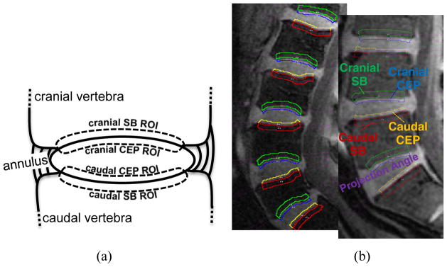
Fig. 2.
(a) Schematic diagram of IVD and adjacent vertebral bodies and ROIs. ROIs were named according to their positions relative to the adjacent IVD. (b) ROIs and corresponding projection planes (magenta straight lines) are shown for two different subjects. Note the subject-to-subject variations in the geometry of endplate surfaces

