
Figure 1.
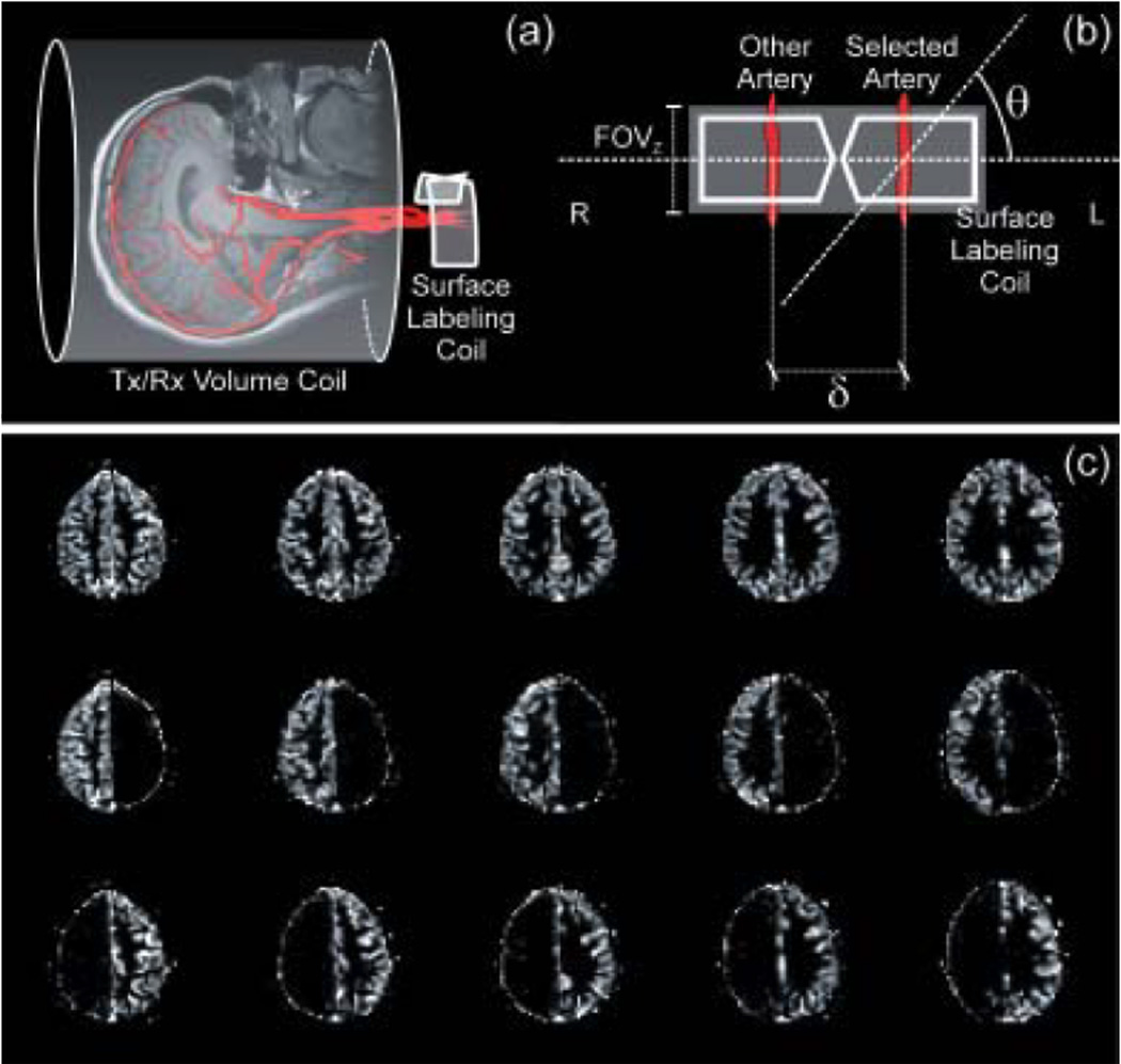
(a) Schematic representation of the separate labeling/imaging coil approach. The labeling RF coil is placed right over the neck to access both CCAs and VAs. (b) An oblique labeling plane, employed at an angle θ with respect to a plane perpendicular to blood flow, allows for selective labeling of the desired arteries. Positive values of θ target the left circulation, while negative values target the right circulation. (c) CBF images of a healthy human subject, obtained by setting θ = 0° (top row), θ = −60° (middle row) and θ = +60° (bottom), corresponding to the CBF images of the whole brain, the right and the left circulation, respectively.