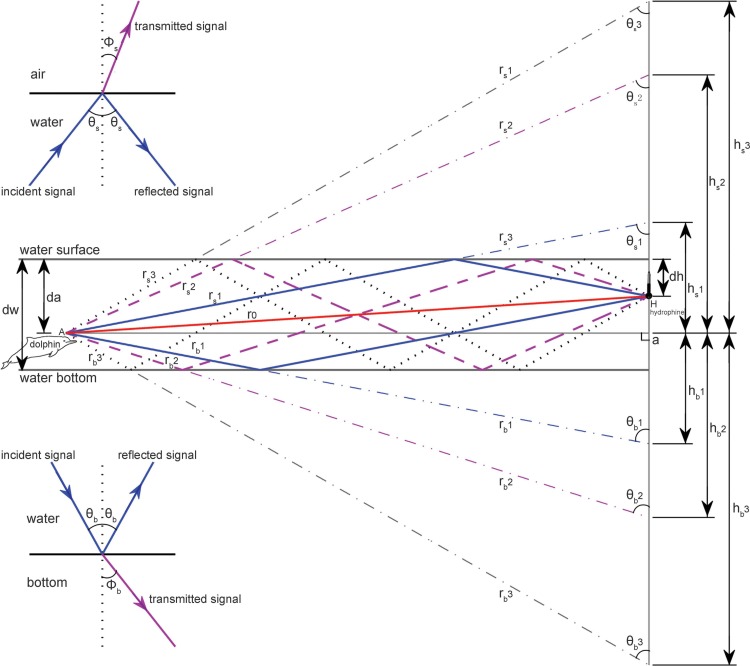
Figure 3. Schematic of multipath propagation.
The dw, da and dh were the depth of the water, the animal, and the receiving hydrophone, respectively. “A” denotes the animal location, and “H” denotes the hydrophone, Aa was the horizontal separation distance between the animal and the hydrophone, r0 was the direct signal propagation path, rs(m) and rb(m) were the signal propagation lengths for multipath propagation signal with a total number of m reflection points and the initial reflection point at the air–water and water–bottom interface, respectively, θs(m) and Φs(m) were the incident (same as reflected) and transmitted angle, respectively, for multipath propagation signal with a total number of m reflection points and the initial reflection point at the air–water interface, θb(m) and Φb(m) were the incident (same as reflected) and transmitted angle, respectively, for multipath propagation signal with a total number of m reflection points and the initial reflection point at the water–bottom interface, hs(m) and hb(m) were the vertical propagation length of the multipath propagation signal with a total number of m reflection points and the initial reflection point at the air–water and water–bottom interface, respectively, by referencing the animal location. The insets show the sound transmission at the air–water interface and at the water–bottom interface, respectively.

