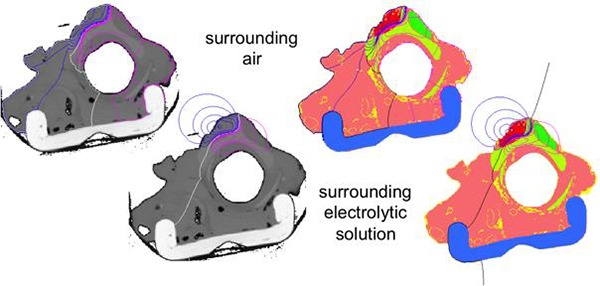
Fig. 4:

Calculated electrical field shown by equipotential lines for anodic (purple) and cathodic (blue) field as well as reference line (left: white, right: black); top: results for surrounding air, bottom: results for surrounding electrolytic fluid, left: superimposed to raw CT-slices, right: superimposed to segmented slices.
