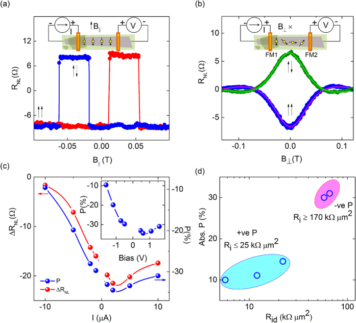
Figure 3. Spin transport and precession measurements at room temperature with spin filtering in Co|h-BN|Gr contact.
(a) Nonlocal spin valve signal (VNL) measured at 300 K using an injection current of I = 10 μA with in-plane magnetic field. Magnetic field sweep directions are indicated by red (up) and blue (down) colors. (b) Nonlocal Hanle spin-precession signal measured as a function of the perpendicular magnetic field with I = 10 μA at 300 K, keeping the magnetization of the ferromagnetic electrodes in an in-plane parallel ( ) and anti-parallel (
 ) configuration. The solid line is the Hanle fit (Eq. 1) to the data points using Eq. 1 for a field T. The nonlocal resistance is defined as
  and
and  −
− . Insets in a and b show the spin valve and Hanle measurement configurations on graphene for a device with spin injection contact of a thicker layer of h-BN and detection under a thinner h-BN with Co electrodes. (c) Dependence of
  and spin polarization
  on the injection bias current at 300 K, Pi and Pd are injector and detector polarizations respectively. Inset: Dependence of P on the injection bias voltage at 300 K. The circles are the data points and the lines are guides to the eye. (d) Absolute value of the spin polarization
  versus the tunnel contact resistance
  for different devices, Ri and Rd are injector and detector resistances. The sign of the spin polarization for the Rid involving high resistance h-BN contact is negative, whereas it is positive for lower resistance devices. Rid = 65 kΩ μm2 corresponds to devices with Ri = 170 kΩ μm2 and Rd = 25 kΩ μm2, Rid ≈ 25 kΩ μm2corresponds to a device with Ri ≈ Rd ≈ 25 kΩ. The spin polarization becomes negative when Ri increased from 25–170 kΩ μm2due to an effective increase in h-BN thickness.

