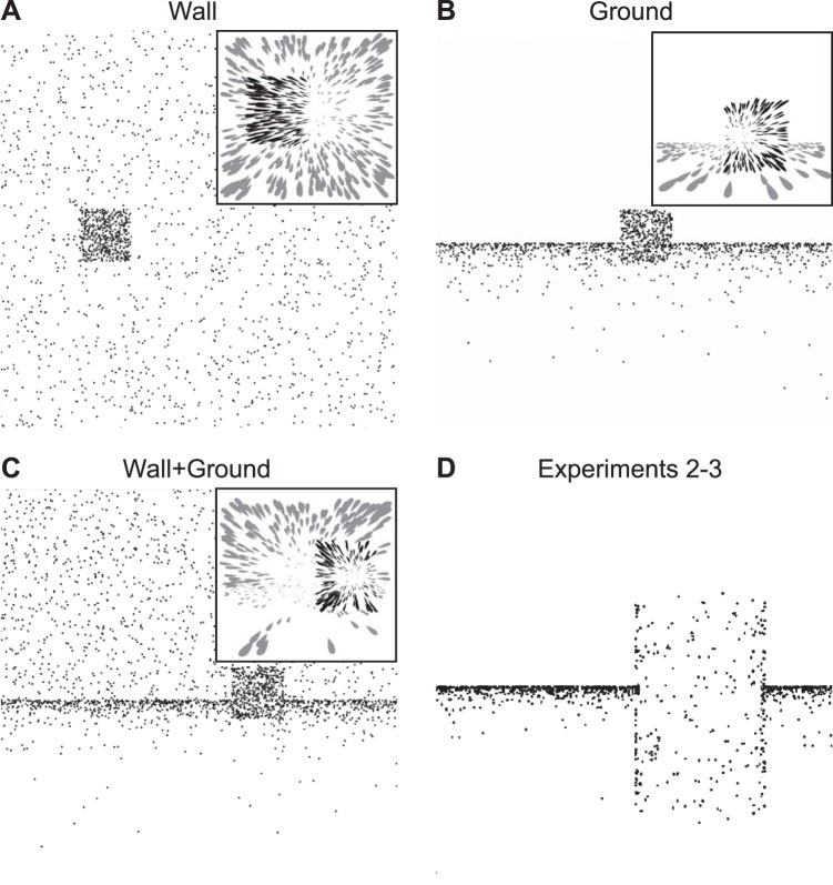
Fig. 3.
Views of the visual environments used in Experiment 1 (A–C) and in Experiments 2–3 (D). In Experiment 1, dots are distributed along either a frontoparallel plane (Wall condition; A), a ground plane (Ground condition; B), or both (Wall+Ground condition; C). Sample optic flow experienced by the observer is depicted in the insets. In Experiments 2–3, a ground plane was used with a cylindrical object (D).

