Fig. 5.
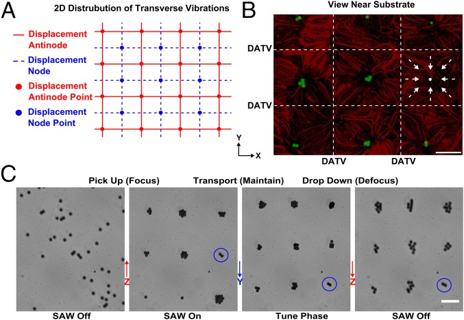
Three-dimensional acoustic manipulation. (A) Illustration of the 2D distribution of transverse vibrations on the substrate. Blue lines represent displacement nodes of transverse vibrations that have minimal vibration amplitudes; red lines represent displacement antinodes. (B) Superimposed images of 3D trapping and streaming patterns; 10-μm green fluorescent polystyrene particles were trapped into a suspended array of single dots, and 1-μm red fluorescent polystyrene particles tracked the motion of the acoustic streaming vortex (the arrows indicate the direction of the streaming near the substrate surface). (C) The image sequence shows the 3D trapping and manipulation of particles with a stable array configuration. A trapping node (blue circle) can levitate particles along z axis (moving into focus) and pushing particles together, transporting them along y axis and dropping them back toward the substrate (moving out of focus). (Scale bar: 100 μm.)

