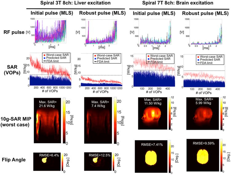
Fig. 8.

Evaluation of the proposed method for LS design of spiral pulses. The two first columns correspond to the tailored excitation of the liver in the 3T eight-channel body model. The last columns show the result of the technique for brain excitation in the 7T head model. The worst case SAR in both scenarios was calculated for a maximum deviation of 15% for the amplitude and 12° in the phase. The first row shows the original pulses as well as those modified to be robust in the presence of transmit errors. The second row shows the SAR distribution across VOPs of the original pulse (in blue) and its worst-case SAR version (in red). Horizontal black lines indicate the FDA SAR limits. The third row shows MIPs of the worst-case SAR distribution of all pulses. In the last row the achieved flip angle maps are displayed. Worst possible SAR values because of errors are severe when the proposed strategy is not applied. In cases where the worst-case SAR is large compared with the tolerated SAR limit, incorporation of the worst-case SAR information in the pulse design may result in a significant worsening of the flip-angle excitation profile. However, in the examples studied in this work we found that the quality of all excitation profiles remained acceptable even after scaling the SAR constraints using the worst-case SAR information.
