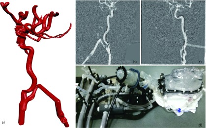
FIG. 4.
Vascular head phantom: (a) surface rendering of the vascular structure within the head phantom, created by 3D digital subtraction angiography; (b) fluoroscopic image of the catheter acquired with plane A; (c) fluoroscopic image of the catheter acquired with plane B; and (d) photo of the vascular head phantom with pump to simulate blood flow.

