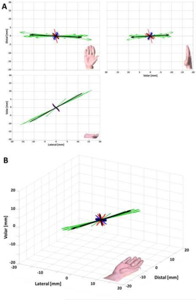
Figure 3.
Orthogonal (A) and isometric (B) views of the specimen specific principal stiffness components for the wrist structure. The 1st, 2nd, 3rd, and averaged principal components are shown (green, red, blue, and black respectively) with length corresponding to stiffness magnitude. Note: the hands shown are for orientation purposes and are not to scale.

