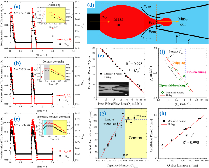
Figure 6. Oscillation of inner liquid tip.
(a–c) Evolutions of nondimensional tip diameter dtip/Df (red) and capillary number Catip (black) at the focusing orifice in tip-multi-breaking mode. Df = 210 μm. (a) Descending behavior of dtip/Df and Catip measured from Fig. 2a with L = 372.7 μm, and period T = 160 ms. (b) Constant-decreasing behavior of dtip/Df and Catip measured from Fig. 2b with L = 537.5 μm, and period T = 456 ms. (c) Increasing-constant-decreasing behavior of dtip/Df and Catip measured from Fig. 2c with L = 919.6 μm, and period T = 834 ms. The insets in (a–c) display the magnifications of tip evolution and temporal variation of Catip. Since no droplet is generated during the initial period of increasing tip diameter (white area), we focus on the later stages of tip-diameter increasing (cyan area), constant tip-diameter (gray area) and tip-diameter decreasing (yellow area) where droplets are generated in (a–c). (d) Schematic of the control volume of the inner liquid tip confined by the left injection nozzle and right focusing orifice. pin and pout are pressures at the focusing orifice for inner and outer phases, respectively, while pno is the inner fluid pressure at the injection nozzle. (e) Log-log plot of oscillation period T versus inner fluid flow rate Qin, with Qout = 1.5 mL h−1. Inset: snapshot of a droplet-sequence generation. Scale bar, 200 μm. (f) Transition boundary of tip-multi-breaking mode in Qout-Qin plane; data adapted from ref. 37. (g) Minimum oscillation period Ts versus capillary number Cafocus. (h) Log-log plot of oscillation period T versus Orifice distance L for fixed inner and outer flow rates. Qin = 4.5 μL h−1, Qout = 3 mL h−1. The device used in (e,g,h) is case L with geometrical dimension shown in Table 1.

