Figure 1.

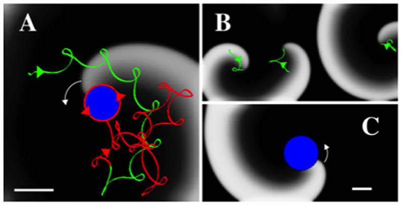
Conversion of AF to AT. A. Snapshot of anchoring of a counter clockwise spiral wave (white arrow) by introduction of a non-conducting ablation lesion. Activation is shown using a gray scale with white indicating activated tissue and black indicating recovered tissue. The spiral tip trajectory before the introduction of the lesion is shown in green and meanders, resulting in AF-like activation. The creation of a lesion (blue disk) progressively anchors the trajectory (shown as the red trajectory) that converges to a regular AT (counterclockwise red arrows). The tissue has as size 5cmx5cm, and Rabl=0.4 cm. The direction of the tip trajectories are indicated by arrows. B, C. Snapshots before (B) and after (C) the introduction of a circular lesion (blue, Rabl=1 cm) in a larger computational domain (10cmx5cm) with period boundary conditions in the horizontal direction. Before the introduction of the lesion (B) the domain harbors three spirals with tip trajectories indicated in green and direction by arrows. After the lesion (C), a single activation front is stably anchored at the lesion, resulting in regular activation. Scalebars: 1 cm.
