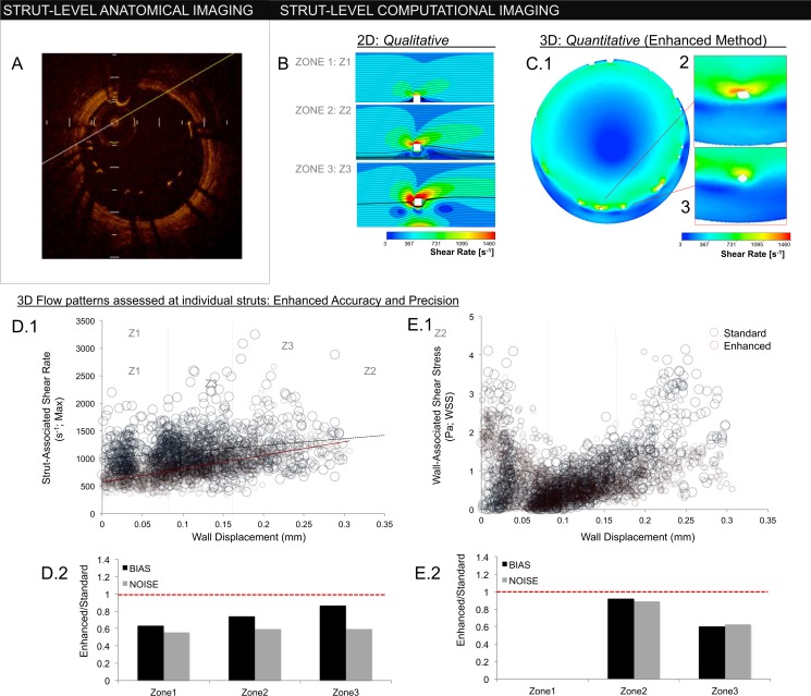
Fig 6.
(A) In-plane OCT frame depicting strut-wall displacement (WD). Struts with WD greater than a single strut thickness (>80 um) are malapposed. (B) 2D simulations of flow around an idealized ‘strut’ (white square; 80 μm x 80 μm). Flow disturbances are influenced by WD, demonstrated for WDs of 80 μm, 160 μm, and 320 μm in zones 1, 2, and 3, respectively (zone 1≤80 μm; 80 μm <zone 2≤160 μm; 160 μm<zone 3). Enhanced reconstruction permits detailed hemodynamic characterization in 3D patient-specific settings. (C.1) In-plane, cross-sections of the implant hemodynamic microenvironment. As with 2D simulations, flow disturbances around struts (white) increase with WD. (C.2), (C.3) Unlike idealized 2D simulations, inter-strut variability exists despite similar anatomic strut position–a phenomenon reliant on 3D effects. Hemodynamic accuracy requires accurate definition of implant geometry, demonstrated by comparing flows generated from the enhanced and standard interpolation methods. (D.1) Strut-associated shear rate correlated strongly with WD in the enhanced method (red circles; slope = 2447 μm-1s-1; r2 = 0.45), though the association was blunted and dispersed with standard interpolation (blue circles; slope = 1221 μm-1s-1; r2 = 0.05). (D.2) Bias, defined as ratio of mean value in each zone between the enhanced and standard method, was reduced in all zones. Noise, defined as ratio of standard deviations in each zone, was also reduced. (E.1), (E.2) Wall shear stress (WSS) demonstrated a “U” type relationship, being high in zone 1 when struts contacted vessel wall (here, WSS is defined on the upper surface of the strut). As contact was lost, WSS decreased reflecting flow shielding between strut and wall (zone 2). With further strut displacment (zone 3), WSS recovered to levels observed in zone 1. Again, the enhanced method (red circles; in E.1) demonstrated reduced noise and bias compared to the standard approach (blue circles; E.1). The largest discrepancies in the standard method were in regions of highest malapposition (zone 3), where discontinuous reconstructions cannot maintain an adequate flow barrier.

