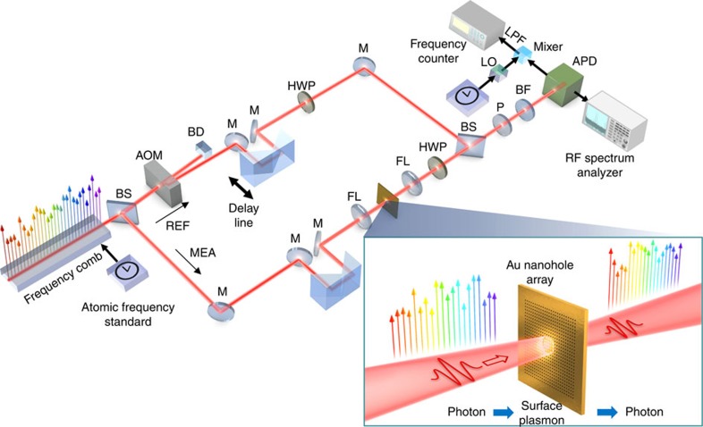
Figure 1. Generation and characterization of plasmonic frequency comb.
Part of the frequency comb experiences plasmonic mode conversion by passing through the plasmonic sample. The sample consists of a subwavelength nanohole array on an Au thin-film, enabling the conversion from photon to SP (from SP to photon). The other part of the frequency comb is used as a reference beam to compare with the frequency comb passed through the plasmonic sample. The frequency combs at two different paths are combined and monitored by APD. The characteristics of the frequency comb at measurement path are analysed by an RF spectrum analyser and a frequency counter. APD, avalanche photo-detector; BD, beam dumper; BF, band-pass filter; BS, beam splitter; FL, focusing lens; HWP, half-wave plate; LO, local oscillator; LPF, low-pass filter; M, mirror; MEA, measurement beam path; P, polarizer; REF, reference beam path.

