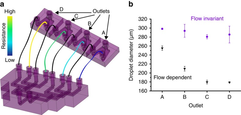
Figure 3. Setup and performance of unbalanced parallel network.
(a) Schematic of the parallel network assembled by connecting a distribution manifold to four droplet generators. The continuous phase was linked using low resistance jumper tubing (ID=762 μm) and the dispersed phase was linked using various lengths of tubing (ID=127 μm) to create a gradient of resistances across the four branches. (b) Droplet diameters (n>1,000) produced by the four branches of the parallel network (left) by dispersed and continuous phase flow rates of 10 and 70 ml h−1 (purple circles) and 30 and 210 ml h−1 (black triangles) while operating in and beyond the flow invariant regime, respectively. Error bars represent the s.d.

