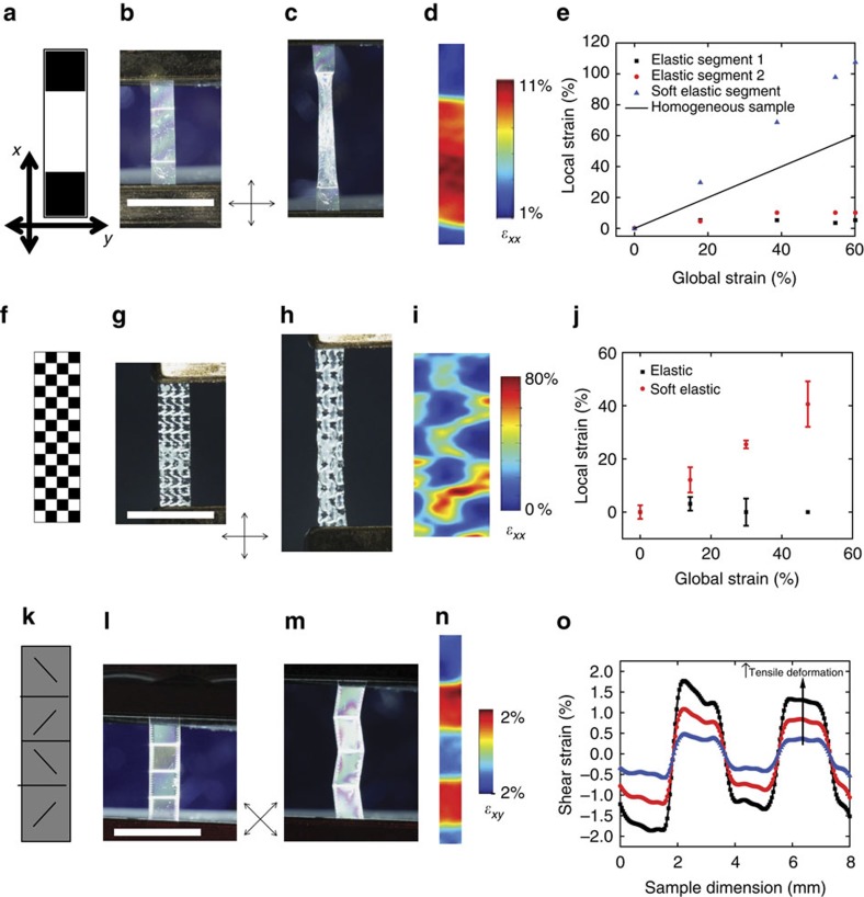
Figure 2. Both extensional and shear strain can be controlled in 2D.
The desired pattern of modulus is indicated in a,f and k when loaded along the long axis of the film. Black pixels correspond to elastic regions while white pixels correspond to soft elastic regions. Grey scale values are indicative of angle of the director. Images of the fabricated LCE film with the desired director pattern (b,g,l) and after straining (c,h,m) between crossed polarizers. 2D DIC is used to map the strain of the sample (d,i,n) at 12% global tensile strain. For patterns with only elastic and soft elastic regions (d,i) extensional strain is shown. Shear strain is shown for n. Strain is plotted on the undeformed sample grid. The local extensional (e,j) and shear (o) strains for these heterogeneous films are shown for distinct director orientations as a function of global extensional strain. Error bars (j) indicate s.d. of n=5 regions of the same director orientation. Shear strains (o) are shown along the sample lengths at 4, 8 and 12% global tensile strain. Crossed arrows indicate the orientation of the polarizer and analyser for photographs. Scale bars, 6 mm.

