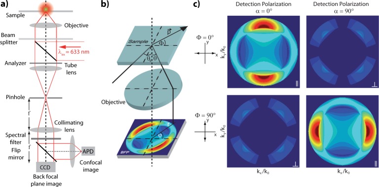
Figure 6.
(a) Confocal real space imaging and BFP imaging setup. (b) Scheme illustrating the BFP radiation pattern created by a point-dipole emitter. p⃗, dipole moment; Φ, orientation angle of dipole axis in sample plane; θ, emission angle; θs, incident angle complementary to θ; ϕ, azimuthal angle in back aperture; r, radial distance from optical axis.19 (c) Calculated BFP patterns of an in-plane point dipole on an air–glass interface oriented with Φ = 0° recorded for parallel (Φ = 0°, α = 0° and Φ = 90°, α = 90°) and crossed polarization (Φ = 0°, α = 90° and Φ = 90°, α = 0°), with α the orientation of the analyzer transmission (detection polarization). The emission detected for cross-polarization is due to polarization mixing caused by the air–glass interface.

