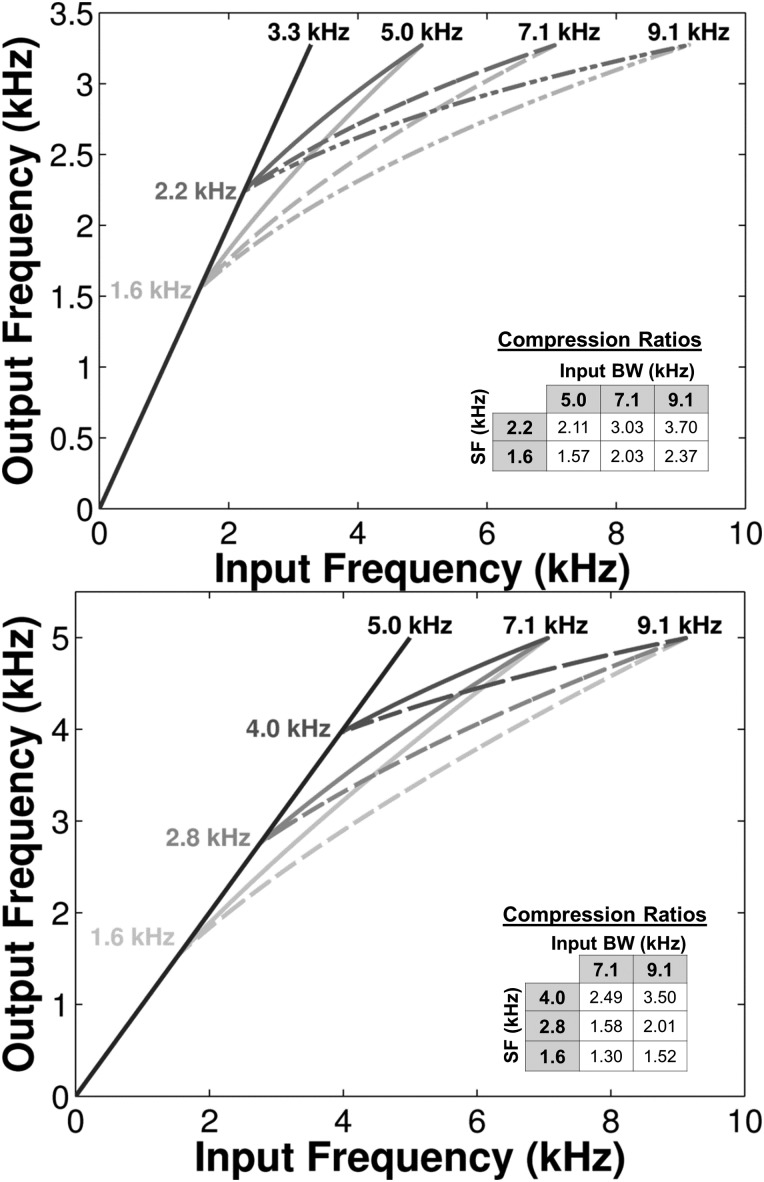
FIG. 4.
The frequency input-output functions and the NFC parameters used to derive them for group MS and group MM (top and bottom panels, respectively). Each SF is represented by a different shade of gray. For each SF, the desired input BWs were achieved by the selection of CR (see inlet for values).

