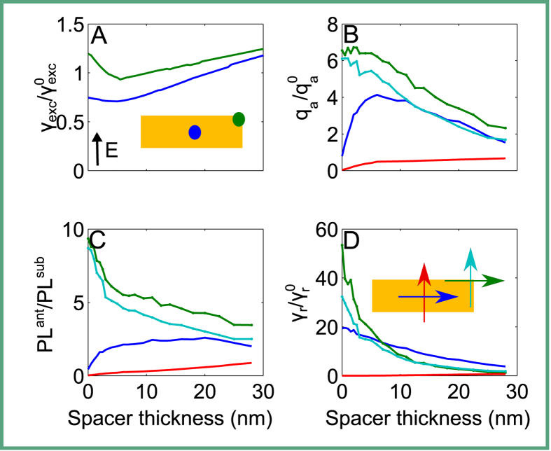
Figure 5.
(A) The excitation rate of the electric field of a plane wave in the characteristic points of the antenna (center [dark blue] and a top-end corner [green]), normalized to the intensity of a plane wave in a setup without the antenna. The illumination plane wave is polarized along the short axis of the antenna as indicated by the inset arrow. (B) quantum yield, (C) fluorescence enhancement, and (D) radiative decay rate enhancement for a dipole emitter placed above the center of the antenna and polarized parallel to its long (dark blue) or short (red) axis; the quantities were calculated also for the case where the dipole emitter was placed above the top-end corner of the antenna and parallel to its long (green) or short (light blue) axis.

