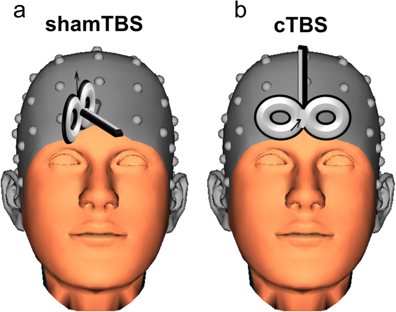
Figure 4. Graphical illustration of the TMS coil.
The head was taken from the BrainVision Analyzer 2.1 software package (http://www.brainproducts.com/productdetails.php?id=17) and it shows the used electroencephalogram electrode grid. Both of the figures show the direction of the magnetic field by the black arrow. Contrary to the cTBS condition (right Figure part b), in the sham condition the coil is orientated at the 90 degree angle and a piece of rubber was placed between the TMS coil and head, so the magnetic field or any residual magnetic influences do not affect the frontopolar cortex(left Figure part a).

