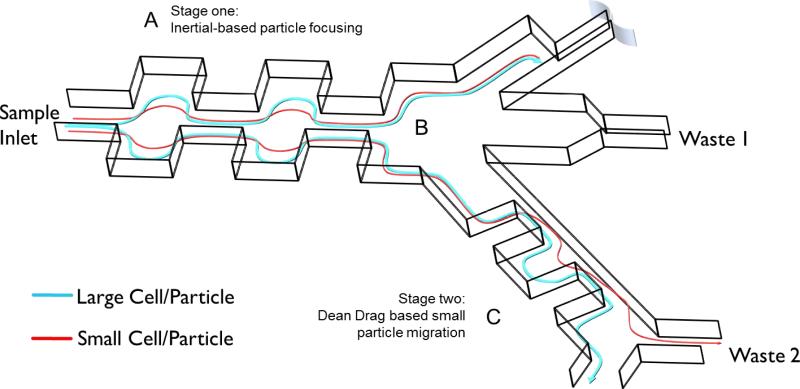
Fig. 1.
Complete schematic of multistage separator device. A) Stage 1: Particles are focused to the outer walls of the microchannel through a balance of wall lift and shear gradient lift forces. The contraction and expansion widths and lengths are 60 and 180, respectively. Stage one consists of 50 symmetric contraction expansion pairs. B) Trifurcating junction between stages. C) Stage 2: The inertial focused streamlines are exposed to dean drag forces where small particles migrate to different equilibrium positions. Stage 2 dimensions are defined as: expansion width and length are 300 and 900, respectively and the contraction width and lengths are 50 and 900, respectively. Stage 2 consists of 10 pairs of asymmetric contraction expansion pairs.

