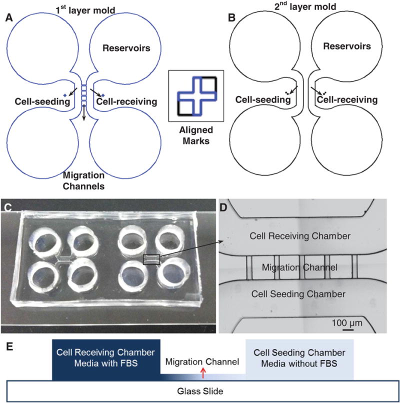
Figure 1.

Schematic diagram of the molds for fabrication of the gradient device. (A) The first shallow mold layer (16 μm) to define four reservoirs, cell-seeding/receiving chambers, and five migration channels. (B) The second mold layer to define four reservoirs and cell-seeding/receiving chambers. The square box shows the alignment marks on both layers. (C) Two devices fabricated and bonded on one glass slide; the size of the two devices together is 2 × 4 cm. (D) Image shows the cell-receiving chamber, the migration channels, and the cell-seeding chamber, respectively; the scale bar is 100 μm. (E) Schematic view of the cross section of the device shows different heights of the cell chambers and migration channels.
