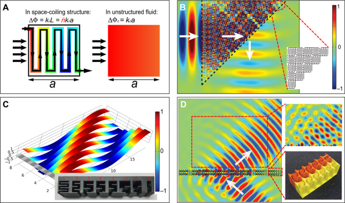
Fig. 7. Space-coiling and acoustic metasurfaces.

(A) An example of the space-coiling structure and the relevant sound pressure field inside (84). The color indicates the phase of the propagating sound wave. Here, a large phase delay Δφ ≫ Δφ0 = k0a can be caused by the coiled channels, where k0 is the wave vector in the background fluid and a is the exterior dimension of the cell. With proper design, such structures can be used for many novel effects, such as the negative-refracting prism shown in (B) (84). Here, space-coiling unit cells are assembled into a prism. Sound incidents from the left, and encounters of negative refraction as it emerges from the prism, are indicated by white arrows. Red/blue represents positive/negative pressure. (C) A design of reflective acoustic metasurface that is capable of generating phase changes up to 2π. This can be seen from the color (red and blue represent positive pressure and negative pressure, respectively) and the undulations of the stripes (108). The metasurface is shown on the lower left, and the wave is incident normally on the surface. The ridge of red stripe sections indicates the emergence of a reflected wave at a nonspecular angle. Inset: Implementation of a slightly modified space-coiling design of the metasurface, with a lateral gradient of phase delays (109). (D) A design of the metasurface that generates negative refraction for the transmitted wave. Left: The simulation result (white arrows delineate incident and refracted beam directions). Right: The experimentally measured pressure map (113) (red and blue represent positive pressure and negative pressure, respectively) (top) and a photographic image of a section of the actual sample (bottom).
