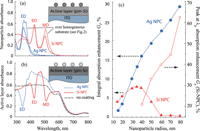
Figure 6.
(a) Spectra of the light absorbance of the NPC placed over the photovoltaic element shown in Fig. 5. Lines with marks correspond to absorbance spectra of NPC placed over the homogeneous substrate [also shown in Fig. 2(a)]. Inset: schematic view of the structure; shaded region indicates where absorbance is calculated. (b) Absorbance inside the active layer (the region shown shaded in the Inset). (c) Integral absorbance enhancement for Ag-NPC and Si-NPC. The resonant absorbance enhancement at λp due to Kerker-type effect is also shown at secondary axis of the ordinates. The calculations in (a,b) were performed for Ag-NPC RAg = 30 nm, dAg = 125 nm and for Si-NPC RSi = 60 nm, dSi = 250 nm.

