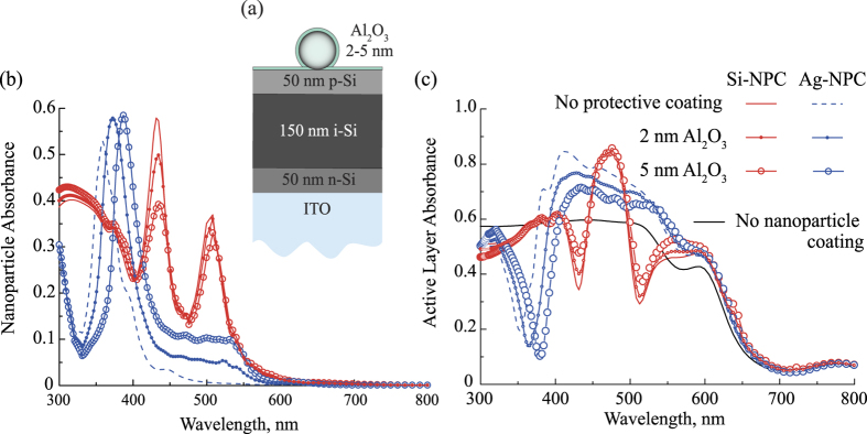
Figure 7.
(a) Scheme of the structure shown in the Fig. 5 with added protective coating of Al2O3. (b) Spectra of the light absorbance of the NPCs placed over the photovoltaic element shown in Fig. 5 (solid line for Si-NPC and dashed line for Ag-NPC) are compared with the similar spectra for the structure shown in Fig. 7(a) (lines with scatters). (c) Absorbance inside the active layer shown in Fig. 5 (solid line for Si-NPC and dashed line for Ag-NPC) are compared with the similar spectra for the structure shown in Fig. 7(a) (lines with scatters). The calculations in (b,c) were performed for Ag-NPC RAg = 30 nm, dAg = 125 nm and for Si-NPC RSi = 60 nm, dSi = 250 nm.

