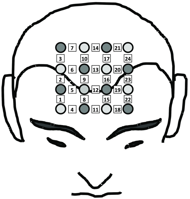
Fig. 3.
Optical helmet configuration. Light gray circles correspond to the illumination fibers, dark gray circles correspond to the detection fibers. The squares indicate the measurement channels, numbered from 1 to 24, which correspond to the tissue regions between each source–detector pair used for NIRS measurements.

