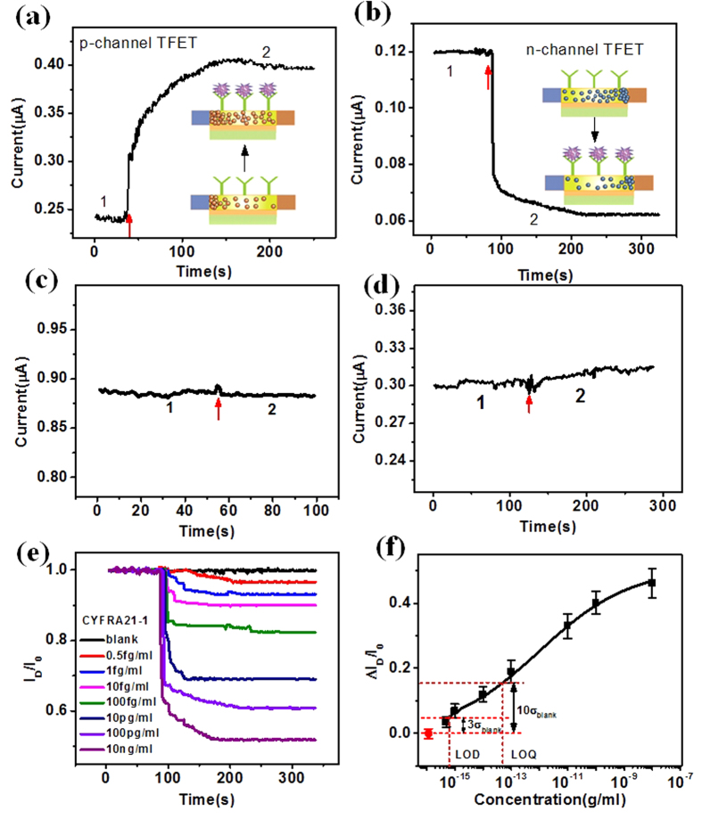
Figure 4. Real-time detection of CYFRA21-1 with the SiNW-TFET based biosensor.
(a,b) Plots of SiNW-TFET current change versus time for real-time CYFRA21-1 detection for VD = 1 V and VG = −3 V(a) VG = 2 V (b). Region 1 stands for the flow of buffer solution (0.01× PBS) and region 2 for the addition of 100 pgml−1 CYFRA21-1. The insets demonstrate the change of surface electrostatic environment and carrier in the SiNW channel. (c,d) Plots of current versus time for the unmodified SiNW-TFET (c) and the anti-CYFRA21-1-modified SiNW-TFET based sensor (d). Region 1 stands for the flow of buffer solution and region 2 for the introduction of 100 pgml−1 CYFRA21-1 (c), 1 nM of CEA (d). (e) Plots of normalized current change versus time with CYFRA21-1 at a series of concentrations (0.5 fgml−1, 1 fgml−1, 10 fgml−1, 100 fgml−1, 10 pgml−1, 100 pgml−1, and 10 ngml−1) for an anti-CYFRA21-1 modified SiNW device at VD = 1 V and VG = 2 V. (f) Plot of current change as a function of the logarithm of CYFRA21-1 concentration. The LOD and LOQ equal to three and ten times of the standard deviation of blank response.

