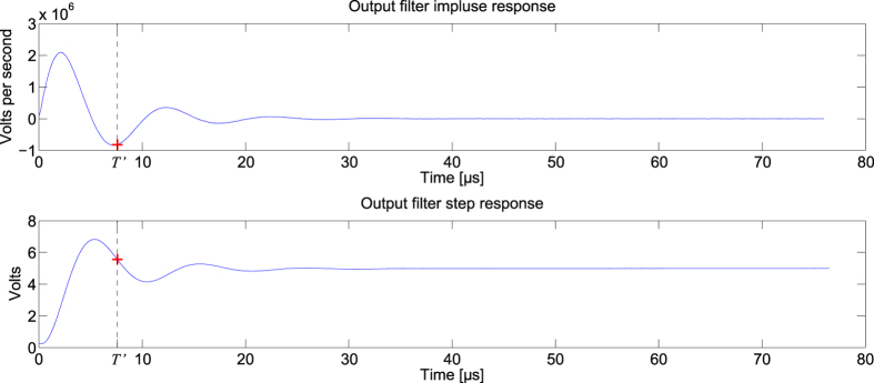
Figure 5. Impulse and step responses of the analogue readout layer used for the equalization of a nonlinear channel.
The step response is recorded at the beginning of the experiment. Its derivative gives the impulse response of the analogue readout layer. The red cross gives the signal value at T’ = 7.598 μs.

